Yaskawa APOGEE FLN P1 User Manual
Page 21
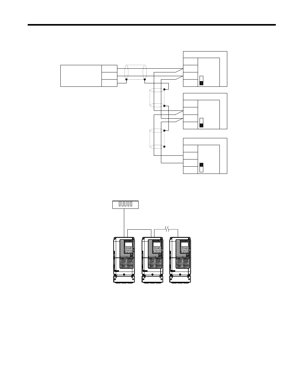
explains the wiring for multiple connections.
CONTROLLER
IG
+
-
SHLD
+
-
SHLD
DRIVE
SI -J3
N2-P1
S1
ON
S1
OFF
IG
+
-
SHLD
DRIVE
SI-J3
N2-P1
S1
OFF
IG
+
-
SHLD
DRIVE
SI-J3
N2-P1
Figure 9 Connection Diagram for Multiple Connections
Drive Drive Drive
Metasys N2 or
APOGEE FLN P1
Field Controller
A1000
CIMR-AU5A0009FAA
600V 3Phase 5.5kW/3.7kW
A1000
CIMR-AU5A0009FAA
600V 3Phase 5.5kW/3.7kW
A1000
CIMR-AU5A0009FAA
600V 3Phase 5.5kW/3.7kW
Figure 10 System Overview-Connecting Multiple Drives to the Network
The two ends of the network must be terminated with a 120 ohm resistor between the “+” and
“-” and signals. The SI-J3 has a built in termination resistor that can be enabled or disabled
using DIP switch S1. If a drive is located at the end of a network line, enable the termination
resistor by setting DIP switch S1 to the ON position. Disable the termination resistor on all
slaves that are not located at the end of the network line by setting DIP switch S1 to the OFF
position (The factory setting for DIP switch S1 is OFF).
5 Installation Procedure
YASKAWA TOEP YAICOM 13 Metasys N2 & Apogee FLN P1 SI-J3 Installation & Technical Manual
21