5 installation procedure – Yaskawa BACnet MS/TP SI-B3/V User Manual
Page 26
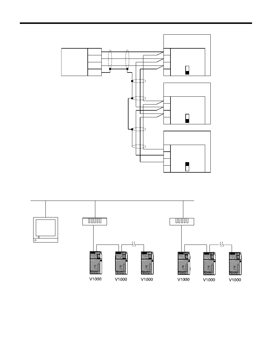
Router
1
2
3
4
+
-
SHLD
Drive
S1
OFF
SHLD
TXRX-
TXRX+
IG5
1
2
3
4
Drive
S1
OFF
SHLD
TXRX-
TXRX+
IG5
ON
1
2
3
4
Drive
S1
SHLD
TXRX-
TXRX+
IG5
SI-B3/V
BACnet
COMMON
SI-B3/V
BACnet
SI-B3/V
BACnet
Figure 18 Connection Diagram for Multiple Connections
BACnet
MS/TP
BACnet over Ethernet or BACnet/IP
Router
Router
MS/TP
STOP
(Hz)
(Hz)
(A)
(V)
V1000
STOP
(Hz)
(Hz)
(A)
(V)
V1000
STOP
(Hz)
(Hz)
(A)
(V)
V1000
STOP
(Hz)
(Hz)
(A)
(V)
V1000
STOP
(Hz)
(Hz)
(A)
(V)
V1000
STOP
(Hz)
(Hz)
(A)
(V)
V1000
Figure 19 Connecting Multiple Drives to a BACnet Workstation – System Overview
The two ends of the BACnet network must be terminated with a 120 ohm resistor
between the “+” and “-” and signals. The SI-B3 has a built in termination resistor that
can be enabled or disabled using DIP switch S1. If a drive is located at the end of a
5 Installation Procedure
26
YASKAWA TOEP YAICOM 19A V1000 Option BACnet MS/TP SI-B3/V Installation & Technical Manual