4 interconnection diagram with vs-616g5 – Yaskawa Varispeed-656 DC5 User Manual
Page 30
E-20
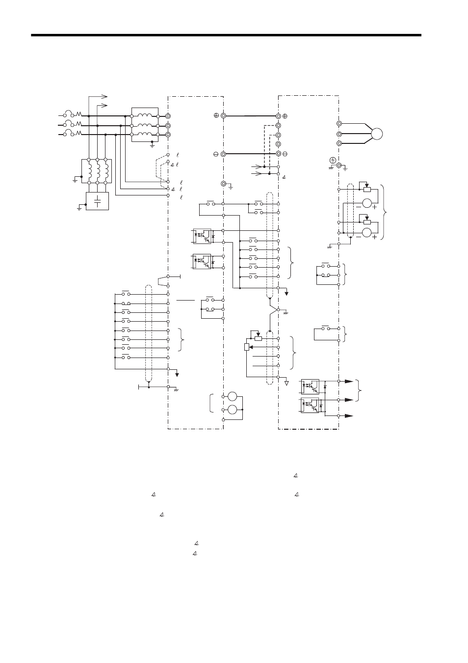
3.4
Interconnection Diagram with VS-616G5
* 1. Do not connect a power supply to the VS-616G5 AC power supply terminals R/L1, S/L2, and
T/L3.
* 2. For the VS-616G5 models provided with cooling fan terminals r and (200 V Class with 18.5
to 75 kW and 400 V Class with 18.5 to 300 kW), remove the jumper wiring between r and R/
L1, and between
and S/L2. Then take the power supply for r
and
from the VS-656DC5
primary power supply line. The VS-616G5, exclusive for DC input, has no jumper wiring.
The terminals r and in the above diagram are the terminal names for 200 V Class VS-
616G5 with 18.5 to 75 kW. These terminal names are as follows respectively for each VS-
616G5 capacity:
y 400 V Class 18.5 to 45 kW: r,
y 400 V Class 55 to 160 kW: r, 400
* 3. Be sure to use the specified AC reactor and harmonics filter for the VS-656DC5, to avoid
abnormal operations.
* 4. Set up a sequence whereby the VS-616G5 starts operation and then the VS-656DC5 starts
after the power supply is turned ON, and the power supply is turned OFF after the VS-
616G5, the motor, and the VS-656DC5 are stopped in this order.
Operating the VS-616G5 without starting the VS-656DC5, or turning OFF the power supply
while the VS-656DC5 is running may cause the VS-656DC5 to malfunction.
-10 to 10 V
Converter
Inverter
Multi-
function
analog
output
18
19
20
Fault contact
output
250 VAC 1 A or less
30 VDC 1 A or less
C READY
During MC
motion
25
27
37
26
E
MCCB
*6
*7
1
2
3
4
11
35
36 +24V
12
RUN-SB
STOP
External
fault
Fault reset
Shielded sheath
connection
terminal
Sequence common
5
6
7
8
Multi-
function
contact input
23
21
Multi-function
analog monitor
(Input current)
(Input power)
22
Multi-function
analog output common
Reactor
Capacitor
Harmonics
filter
*3
VS-656DC5
R/L1
S/L2
T/L3
1
Input AC
reactor
*3,*8
U
V
X
Y
R/L1
S/L2
T/L3
VS-616G5
IM
U/T1
V/T2
W/T3
Grounding
A
B
A
B
*2
*1
12
Multi-
function
analog
input
Shielded sheath
connection
terminal
13
14
16
17
15
9
10
C RUN
Sequence common
1
2
FWD run command
REV run command
3
4
External fault
Reset
5
6
7
8
11
Multi-
function
contact
input
*5
*4
18
19
20
Fault contact output
250 VAC 1 A or less
30 VDC 1 A or less
25
26
27
Multi-function
output common
9
10
Multi-function
contact output
250 VAC 1 A or less
30 VDC 1 A or less
3-phase
AC
power
supply
Multi-function
open-collector
output
48 VDC 50 mA
or less
21
23
22
(12)
AM
FM
Grounding
*9, *10
*9, *10
External baseblock
t1/
31
r1/
11
r/
1
/
2
1/
21
r
U
X
V
Y
W
Z
W
Z