5 wiring precautions, Control circuit wiring – Yaskawa Varispeed-656 DC5 User Manual
Page 32
E-22
3.5
Wiring Precautions
The external interconnection wiring must be performed with following procedures. After
completing VS-656DC5 interconnections, be sure to check that the connections are correct.
Never use control circuit buzzer check.
Control Circuit Wiring
Separate control circuit wiring from main circuit wiring and other power cables.
Separate wiring for control circuit terminals from other control circuits or main circuit wir-
ings.
Wiring distance should be 50 m or less.
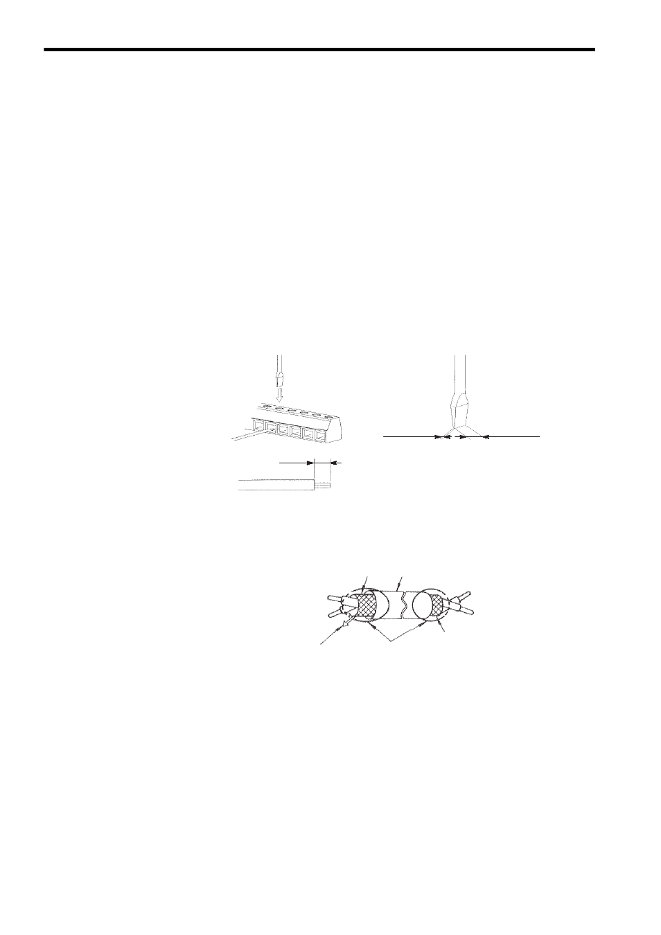
Insert the wire into the lower part of the terminal block and connect it tightly with a screw-
driver.
Fig. 9 Control Circuit Terminal Wiring
Use twisted-pair shielded wire for the control circuit wire and connect the shielded sheath to
VS-656DC5 terminal E. (Refer to Fig. 10.)
Fig. 10 Shielded Wire Termination
0.6 mm max.
3.5 mm max.
5.5 mm
Wire sheath strip length must be 5.5 mm.
Screwdriver Blade Width
Do not connect here.
Connect to shielded sheath
terminal E at VS-656DC5.
Shielded sheath
Armor
Insulate with tape.