Yaskawa Varispeed-656 DC5 User Manual
Page 39
3 WIRING
E-29
* 1. Indicates the terminal number of the control card.
* 2. The input signals excluding RUN-SB signal are status signals. (RUN-
SB signal is a rising trigger signal and held internally.) When RUN-
SB and fault reset signals are input, the input must be held at least 40
ms.
Photocoupler
Output
25 - 27
Multi-function
Photocoupler
Open-collector
Output
Set to “CREADY (Converter
Ready)” prior to shipment.
48 VDC 80
mA or less
26 - 37
Set to “MC Operating (MCON)”
prior to shipment.
Relay Output
18 - 20
19 - 20
FAULT Output
(Transfer Contact)
Outputs when a fault is detected.
Terminal 18-20: Closed during fault
detection
Terminal 19-20: Open during fault
detection
250 VAC 1 A
or less
30 VDC 1 A
or less
9 - 10
Multi-function
Contact Output
Set to “During Converter Running
(During Run)” prior to shipment.
Analog Output
21
Multi-function
Analog Output
Set to “Input power (AC Side
Power)” prior to shipment.
-10 V to +10
VDC or less
23
Set to “Input current (Input Cur-
rent)” prior to shipment.
22
Multi-function
Analog Common
−
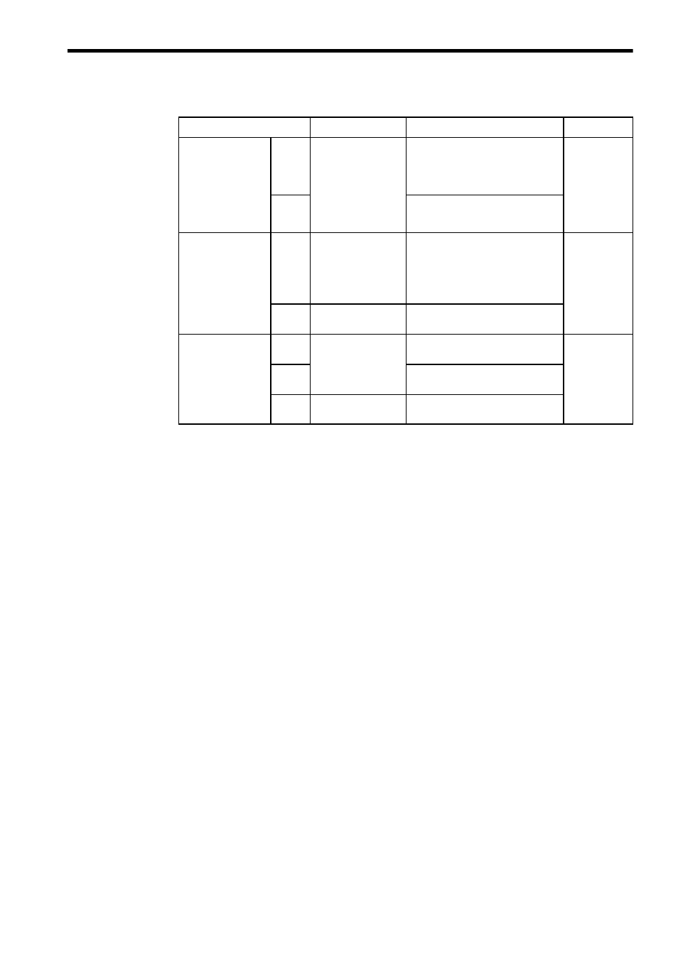
Table 7 Control Circuit Terminal Functions (cont’d)
Terminal Name
*1
Signal Name
Function
Signal Level