Prior to installing the option, Installing the option, Notice – Yaskawa V1000-Series Option SI-EM3D/V Dual Port EtherNet Modbus TCP/IP Technical Manual User Manual
Page 13
NOTICE
Properly connect all pins and connectors.
Failure to comply may prevent proper operation and possibly damage equipment.
Check wiring to ensure that all connections are correct after installing the option and connecting any other devices.
Failure to comply could result in damage to the option.
u
Prior to Installing the Option
Prior to installing the option, wire the drive, make necessary connections to the drive terminals, and verify that the drive
functions normally without the option installed. Refer to the drive Quick Start Guide for information on wiring and connecting
the drive.
u
Installing the Option
DANGER! DANGER! Electrical Shock Hazard. Do not connect or disconnect wiring while the power is on. Failure to comply could result in
death or serious injury. Before installing the option, disconnect all power to the drive and wait at least the amount of time specified on the
drive front cover safety label. After all indicators are off, measure the DC bus voltage to confirm safe level, and check for unsafe voltages
before servicing. The internal capacitor remains charged after the power supply is turned off.
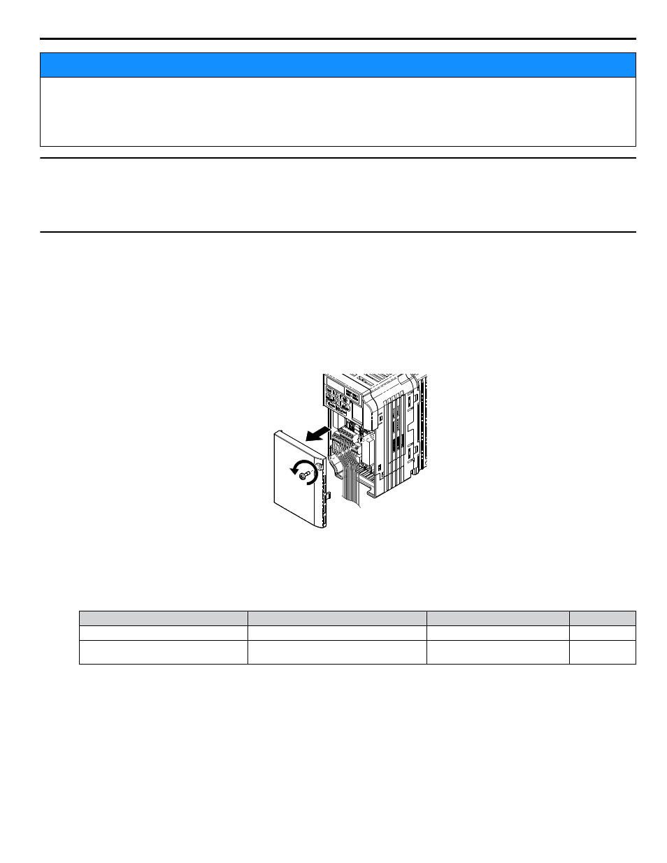
1.
Shut off power to the drive, wait at least five minutes after confirming the DC bus voltage is safe, then loosen the
screw that fastens the front cover in place and remove the front cover. This drive front cover will be replaced by the
option cover. Cover removal varies depending on drive size.
NOTICE: Damage to Equipment. Observe proper electrostatic discharge procedures (ESD) when handling the option, drive, and
circuit boards. Failure to comply may result in ESD damage to circuitry.
Figure 4 Remove the Front Cover
2.
The remaining installation steps differ based on drive model. Find the drive model number on the drive nameplate
and refer to the step indicated in
based on your model number
Table 4 Installation Steps Based on Drive Model
Enclosure Type
Drive Model
Proceed to Step
Page
IP20/Open-Chassis
CIMR-VooAooooB
3
IP20/NEMA Type 1
<1>
CIMR-VooAooooF
6
<1>
Installing the option on an IP20/NEMA Type 1 enclosure drive voids NEMA Type 1 protection while maintaining IP20 conformity.
3.
For IP20/Open-Chassis models CIMR-VooAooooB, remove the bottom cover of the drive by applying pressure
to the tabs on each side of the bottom cover. Pull the bottom cover away from the drive while pushing in on the tabs
to release the cover from the drive. Refer to
for details.
for drive models BA0006B to BA0018B, 2A0008B to 2A0069B, and 4A0001B to 4A0038B, which
require removing the terminal cover prior to removing the bottom cover.
5 Installation Procedure
YASKAWA SIEP YAICOM 17A V1000 Option Dual-Port Modbus TCP/IP SI-EM3D/V Technical Manual
13