Figure 5, Refer to, Figure 6 – Yaskawa V1000-Series Option SI-EM3D/V Dual Port EtherNet Modbus TCP/IP Technical Manual User Manual
Page 14
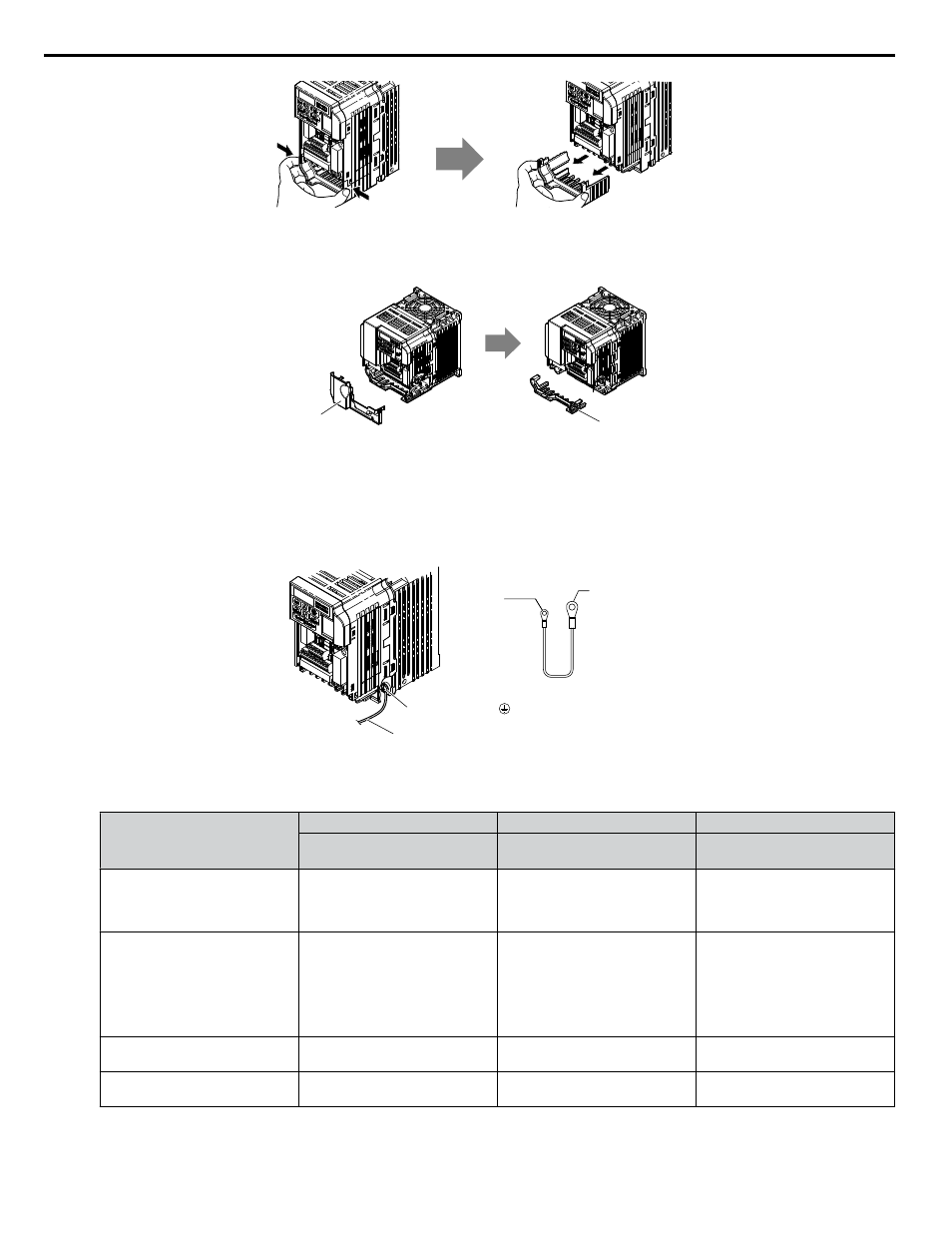
Figure 5 Remove the Bottom Cover on an IP20/Open-Chassis Drive
(Models BA0001B to BA0003B and 2A0001B to 2A0006B)
Bottom Cover
Terminal Cover
Figure 6 Remove the Terminal Cover and Bottom Cover on an IP20/Open-Chassis Drive
(Models BA0006B to BA0018B; 2A0008B to 2A0069B; 4A0001B to 4A0038B)
4.
On IP20/Open-Chassis models, connect the drive side of the ground wire to the drive ground terminal.
Note:
The different ground wires packaged with the option connect the option to different drive models. Select the proper ground wire
depending on drive size. Refer to
for ground wire selection by drive model.
Ground terminal
Ground wire
Drive-side
connector
Screw size:
M3.5 to M6
Option unit
connector
Screw size: M3
Figure 7 Connect the Ground Wire on an IP20/Open-Chassis Drive
Table 5 Ground Wire Selection
Ground Wire Length
(mm/in)
Drive Model
Single-Phase
200 V Class
Three-Phase
200 V Class
Three-Phase
400 V Class
150/5.9
BA0001
BA0002
BA0003
2A0001
2A0002
2A0004
2A0006
–
200/7.9
BA0006
BA0010
BA0012
BA0018
2A0010
2A0012
2A0020
4A0001
4A0002
4A0004
4A0005
4A0007
4A0009
4A0011
250/9.8
–
2A0030
2A0040
4A0018
4A0023
400/15.7
–
2A0056
2A0069
4A0031
4A0038
5.
For IP20/Open-Chassis models, go to Step 9. on page 36.
5 Installation Procedure
14
YASKAWA SIEP YAICOM 17A V1000 Option Dual-Port Modbus TCP/IP SI-EM3D/V Technical Manual