4 ics-10x rear panel, 2 install the converter, 1 stand-alone installation – PLANET ICS-102 User Manual
Page 17: Nstall the, Onverter
User’s Manual of ICS-10x
-12-
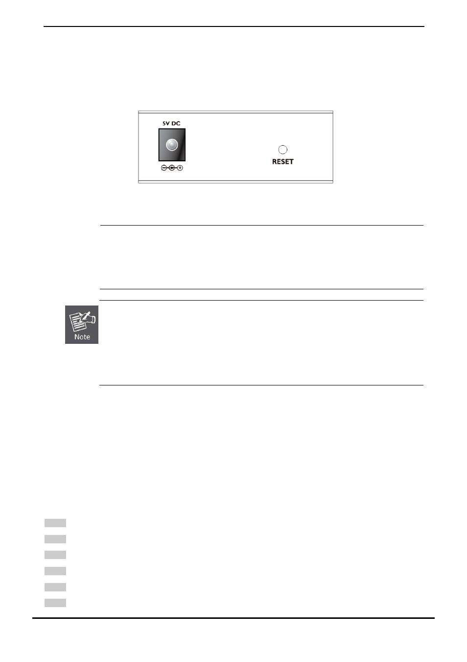
2.1.4 ICS-10X Rear Panel
The rear panel of the converter indicates one DC jack, which accepts input power with 5V DC 2.5A.
■
ICS-10x series
Figure 2-9
Rear Panel of ICS-10x
Power
Notice:
1.
The device is a power-required device, it means, it will not work till it is powered. If your networks
should active all the time, please consider using UPS (Uninterrupted Power Supply) for your
device. It will prevent you from network data loss or network downtime.
2.
In some area, installing a surge suppression device may also help to protect your Media
Converter from being damaged by unregulated surge or current to the converter or the power
adapter.
To press and release the RESET button. The ICS-10x will back to the factory default mode. Be sure that
you backup the current configuration of ICS-10x; else the entire configuration will be erased when
pressing the “RESET” button.
Press and release the RESET button shortly, the device will be rebooted.
Press the RESET button more than 10 seconds, the device will back to the factory default
mode; the entire configuration will be erased.
2.2 Install the Converter
This section describes how to install your ICS-10x Web Smart Media Converter and make connections to the converter.
Please read the following topics and perform the procedures in the order being presented. The hardware installation of
PLANET ICS-10x Web Smart Media Converter do not need software configuration. To install your ICS-10x on a desktop or
shelf, simply complete the following steps.
2.2.1 Stand-alone Installation
To install an ICS-10x stand-alone, on a desktop or shelf, simply complete the following steps:
Step 1
: Turn off the power of the device/station in a network to which the ICS-10x will be attached.
Step 2
: Ensure that there is no activity in the network.
Step 3
: Attach RJ-45 / SC / ST Fiber cable from the ICS-10x to the network.
Step 4
: Attach RS-232/RS-485 cable from the ICS-10x to the want to connect devices.
Step 5
: Connect the 5VDC power adapter to the ICS-10x and verify that the Power LED lights up.
Step 6
: Turn on the power of the device/station; the PWR LED (Green) should light when all cables are attached.