ProSoft Technology PS69-DPS User Manual
Page 100
Reference
PS69-DPS ♦ CompactLogix or MicroLogix Platform
User Manual
Profibus DP Slave Communication Module
Page 100 of 108
ProSoft Technology, Inc.
May 9, 2014
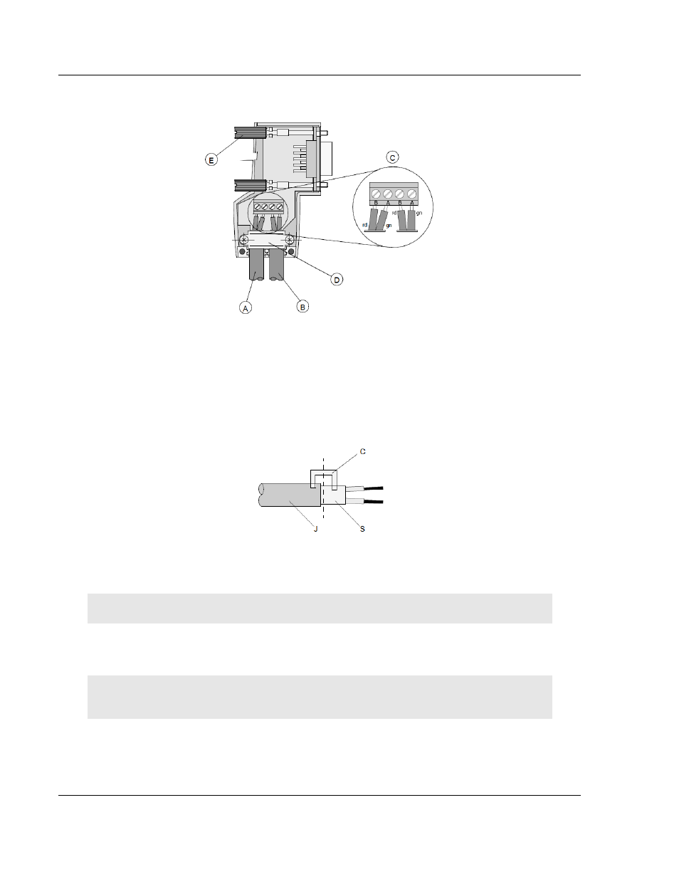
Connection terminal assignment on the PROFIBUS DP:
A Incoming cable
B Outgoing cable
C Connection terminals (only once (B,A))
D Cable cleat for reliving tension
E Bus connector screws
6 Attach the cables with the provided cable cleat to create a robust shielded
connection and to relieve any tension as shown:
J PVC Jacket
S Braided shielding with foil shielding
C Cable cleat
Note: Half of the cable jacket must lie under the cable cleat!
Pay attention to the cable cleat installation instructions.
7 Fasten the individual wires of the PROFIBUS cable to the terminals
8 Close the connector housing.
Note: The shielding of both cables is connected internally with the metal housing of the
connector.
9 Complete the Central Shielding Measures (below) and grounding operations
for the shielding before you connect the cable connector to the module.
10 Plug the PROFIBUS DP connector into the module and secure it with the
screws.