ProSoft Technology MVI46-MBP User Manual
Page 16
MVI46-MBP ♦ SLC Platform
Installing and Configuring the Module
Modbus Plus Communication Module
Page 16 of 101
ProSoft Technology, Inc.
February 19, 2008
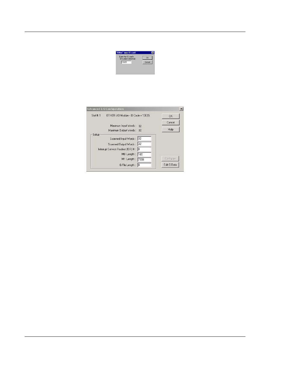
Select the Other module from the list. This action opens the following dialog box.
Enter the module I/O card ID number as 13635, and then click OK. Double-click
the mouse on the module just added to the rack. Fill in the following dialog box
as shown in the following screen example:
Click OK to apply these settings to the module. Then, close the I/O Configuration
dialog box.
The next step is to define the user-defined files to hold status and read/write
database areas.
The last step is to add the ladder logic. If the example ladder logic is used, adjust
the ladder to fit the application. When the ladder example is not used, copy the
example ladder logic to your application and alter as necessary.
The module is now set up and ready to use with your application. Insert the
module in the rack, then attach the serial communication cable to the debug port
and the cable from the application port to the Modbus Plus network. Download
the new application to the controller and place the processor in run mode. If all
the configuration parameters are set correctly, and the module is attached to a
network, the module's Application LED (APP LED) should blink (6 times per
second) and the backplane activity LED (BP ACT) should blink very rapidly. If
you encounter errors, refer to the Diagnostics and Troubleshooting (page 21)
section for information on how to connect to the module's Config/Debug port to
use its troubleshooting features.