ProSoft Technology MVI46-MBP User Manual
Page 41
Reference MVI46-MBP
♦ SLC Platform
Modbus Plus Communication Module
ProSoft Technology, Inc.
Page 41 of 101
February 19, 2008
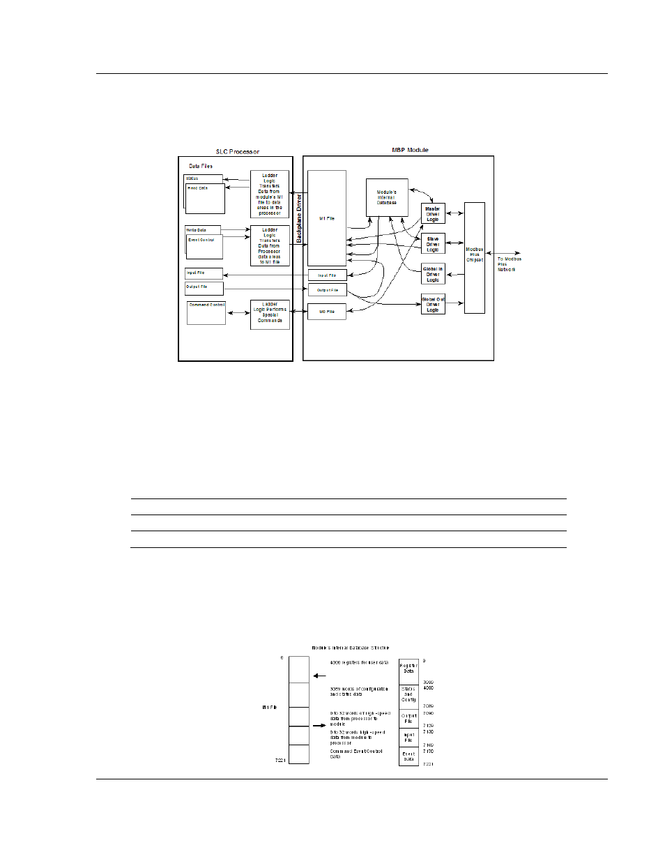
The following illustration shows the data transfer method used to move data
between the SLC processor, the MVI46-MBP module, and the Modbus Plus
network:
As shown in the data flow diagram, all register data transferred between the
module and the processor over the backplane is through the M1 file. Ladder logic
must be written in the SLC processor to interface the M1 file data with data
defined in the user-defined data files in the SLC. All data used by the module is
stored in its internal database. The data transferred from the module to the M1
file is updated when new data becomes available from the Modbus Plus network.
The ladder logic in the SLC can control the module by using M files for command
and module control.
File Offset
Description
M0 0 Command
Control
M1 4370
Module
Control
A value of 9999 in this word (4370 of the M1 file) causes the module to perform a
cold-boot operation.
All data used by the module is stored in its internal database. This database is
defined as a virtual Modbus data table with addresses from 0 (40001 Modbus) to
7221 (4222 Modbus). The following illustration shows the layout of the database: