Slave driver mode – ProSoft Technology MVI46-MBP User Manual
Page 50
MVI46-MBP ♦ SLC Platform
Reference
Modbus Plus Communication Module
Page 50 of 101
ProSoft Technology, Inc.
February 19, 2008
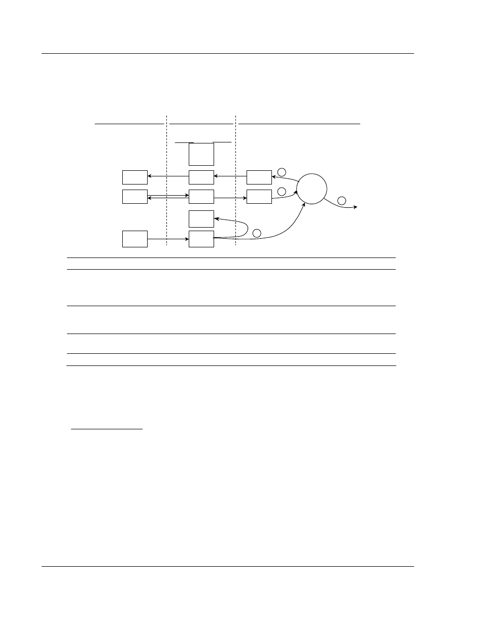
The number of words transferred to the Modbus Plus network is user determined
through the Module Configuration Block described in the Reference chapter. The
following flow chart and associated table describe the flow of data into and out of
the module.
Global Data
Driver
MBP Module
4000
4369
4370
7089
44001
44370
44371
47090
Status
Configuration
Configuration
Data
Status
from Module
Configuration
Status
3
1
2
4
0
40001
Modbus
Addresses
Database
Addresses
User Data
Files
Register
Data
Processor Memory
Backplane Interface
7121
Output File
Data
7090
3999
44000
47091
47122
Output File
Output File
Step Description
1
The Global Output driver reads configuration data from the SLC processor. This data
consists of the number of words to be transmitted by the module each time the module
has the token. In addition, timing data on the update rate for the Global Out transmission
is also obtained from the configuration data.
2
The Global Out data image is updated from the processor through the module's output
image. Based on the update rate configured by the user, the Global Out image in the
Modbus Plus chipset will also be updated.
3
The Global Output driver in the Modbus Plus chipset will transmit the Global Out data
each time the token is received by the module.
4
The Global Output driver status is updated in the module's database.
To enable the Global Output Mode, set the Global Output Length parameter to a
value between 1 and 32. To disable this feature, set the parameter to a value of
zero. Status information about the global output data is found in the status block
transferred from the module to the SLC processor.
Slave Driver Mode
Slave Driver Mode allows the MVI46-MBP module to respond to data read and
write commands issued by other nodes on the Modbus Plus network. Two
aspects of the module's operation must be kept in mind when considering using
this mode:
1
The module supports MSTR Type 1 and Type 2 commands issued from a
Modicon processor or another device acting in a similar capacity.
2
The module is a Modbus Plus Host type of node, therefore any device
wishing to read or write data from the module must be able to define a Data
Slave Input Path in the Routing Path. The module supports all 8 Data Slave
Input paths, but a Data Slave Path of 0 (zero) will cause the command to
be rejected
.