ProSoft Technology MVI46-MBP User Manual
Page 51
Reference MVI46-MBP
♦ SLC Platform
Modbus Plus Communication Module
ProSoft Technology, Inc.
Page 51 of 101
February 19, 2008
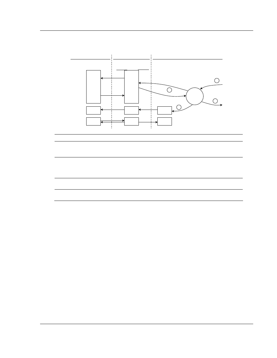
The following flow chart and associated table show the flow of data into and out
of the module.
0
3999
4000
4369
4370
7089
40001
44000
44001
44370
44371
47090
Modbus
Addresses
Database
Addresses
User Data
Files
Slave
Mode
Driver
Status
Configuration
Configuration
Data
Status
from Module
Register
Data
storage
Register
Data
Processor Memory
MBP Module
Backplane Interface
Configuration
Status
3
1
2
4
Step Description
1
A Host device, such as a Modicon PLC or an HMI application issues a read or write
command to the module's node address. The Modbus Plus chipset qualifies the
message before accepting it into the module.
2
After the module accepts the command, the data is immediately transferred to or from
the internal database in the module. If the command is a Read command, the data is
read out of the database and appended to the response, and if the command is a Write
command, the data is written directly into the database.
3
After the data processing has been completed in Step 2, the response is issued to the
originating node.
4
Several counters are available in the Status Block that permit the ladder logic program to
determine the level of activity of the Slave Driver.
There are no special module configuration requirements to place the module in
the Slave Operating Mode. When the module is operating in the slave mode,
external devices act as masters by polling for data from the module or writing to
the module. As such, the module needs to only respond to read and write
commands, transferring data to/from the module's database depending on the
command type.
In order for a Modicon PLC to read data from the MVI46-MBP module, a MSTR
Type 2 instruction must be entered in the Modicon's ladder program. This
instruction initiates a Modbus Plus network transaction between the PLC and the
module. In the configuration of the command, the programmer can specifically
choose the location and amount of data to be read from the module and returned
to the Modicon's memory.
The following illustration shows an example configuration for a MSTR Type 2
command.