Invert phase, Input trim, Input eq and dynamics – MOTU UltraLite-mk3 - Hybrid FireWire/USB 2.0 Audio & MIDI Interface User Manual
Page 67
C U E M I X F X
67
Invert phase
The
Phase
button (Figure 10-3) inverts the phase of
the input signal. For stereo pairs, you can invert the
phase for the left and right channels independently.
Input trim
All UltraLite-mk3 inputs, both analog and digital,
offer continuously variable input trim. In all cases,
trim level can be controlled digitally in 1 dB
increments. This includes the digitally controlled
analog trims on the two mic/guitar inputs and the
six quarter-inch analog inputs on the back panel.
Here is a summary of input trim ranges for each
type of UltraLite-mk3 input:
Once you adjust the trim levels, you can save them
as a file on disk for future instant recall. See “Saving
and loading hardware presets” on page 87 and
“Configurations menu” on page 100.
Input EQ and dynamics
The UltraLite-mk3 lets you apply 7-band
parametric EQ and dynamics processing (DSP) to
any input, analog or digital.
The controls in the EQ/Compression section of the
Inputs tab (Figure 10-3) let you edit EQ and
compression settings within the context of the
channel strip. This is ideal when you are comparing
settings among neighboring channels, or perhaps
even applying the same setting across all inputs.
However, for more detailed editing of EQ and
compression settings for an input channel, you can
click its Focus button and view the settings in the
Channel Section of the CueMix FX window
(Figure 10-1). This section even provides graphical
editing of EQ curves and the compressor graph,
allowing you to click and drag directly on the
graphic. For details see “The channel settings
section” on page 70.
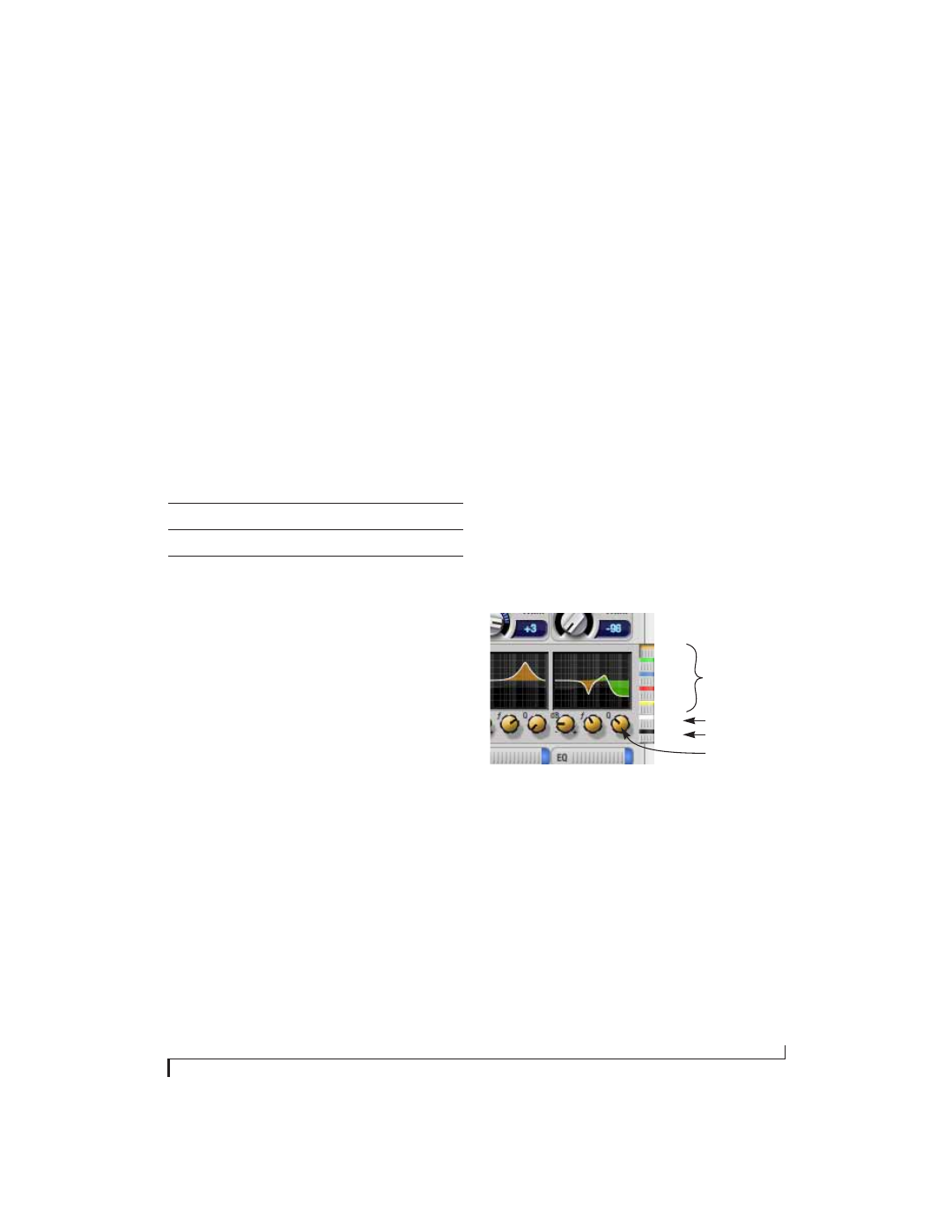
The EQ/Dynamics graph
The EQ/Dynamics graph for each input channel
strip (Figure 10-3) provides a thumbnail view of
the EQ curves or Compressor graph for the
channel. This graphic is for display purposes only;
it cannot be edited directly. To change the EQ
settings in this graph, use the two or three knobs
below, as explained in the following sections. If,
however, you would like to edit the EQ curves
graphically, you can do so in the EQ tab
(Figure 10-10 on page 72).
EQ/Dynamics selectors
The EQ/Dynamics selector buttons along the
right-hand edge of the EQ/Dynamics section
(Figure 10-3) allow you to choose what you are
viewing and editing in the EQ/Dynamics section.
Figure 10-4: The EQ/Dynamics selectors.
Click the selector (Figure 10-4) for the desired EQ
band, low-pass (LP) filter, high pass (HP) filter or
compressor to view it across all channels.
Input
Trim
cut
Trim
boost
Trim
Range
Mic/Guitar
0 dB
24 dB
24 dB
TRS analog inputs
-96 dB
+22 dB
118 dB
S/PDIF (RCA)
0 dB
+12 dB
12 dB
EQ band selectors
LP/HP filter selector
Compressor selector
Colored knobs
Orange
Green
Blue
Red
Yellow
White
Black