The dynamics tab, Enabling dynamics, Compressor – MOTU UltraLite-mk3 - Hybrid FireWire/USB 2.0 Audio & MIDI Interface User Manual
Page 80
C U E M I X F X
80
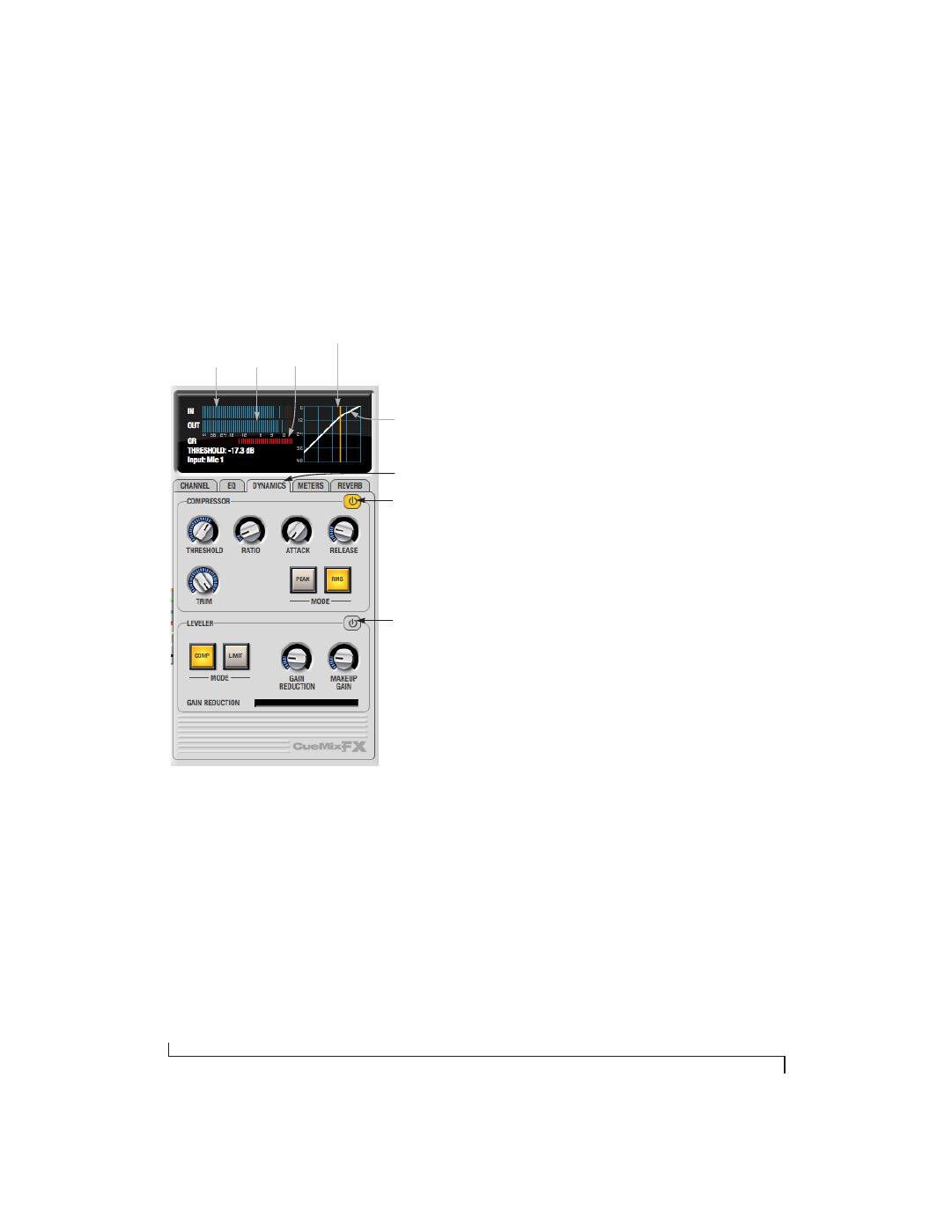
The Dynamics tab
The Dynamics tab (Figure 10-26) displays the
Dynamics processing settings for the input or
output channel that currently has the focus. Click
any focus button in the Inputs or Outputs tab to
view the Dynamics tab settings for the channel.
Figure 10-26: The Dynamics tab.
Enabling Dynamics
Each input and output channel has a global
Dynamics enable/disable
button (Figure 10-3 and
Figure 10-6). This button enables or disables all
dynamics processing for the channel. In addition,
the Dynamics tab has two different dynamics
processors, the Compressor and Leveler, which can
be individually enabled or disabled (Figure 10-26)
for the channel.
Compressor
The
Compressor
(Figure 10-26) lowers the level of
the input when it is above the threshold. The
amount of attenuation is determined by the
Ratio
and the input level. If the input is 6 dB above the
Threshold
and the Ratio is 3:1, then the output will
be 2 dB above the Threshold. When the input level
goes above the threshold, the attenuation is added
gradually to reduce distortion. The rate at which
the attenuation is added is determined by the
Attack
parameter. Likewise, when the input level
falls below the Threshold, the attenuation is
removed gradually. The rate at which the
attenuation is removed is determined by the
Release
parameter. Long Release times may cause
the audio to drop out briefly when a soft passage
follows a loud passage. Short Release times may
cause the attenuation to pump when the average
input level quickly fluctuates above and below the
Threshold.
These sorts of issues can be addressed by applying
the Leveler instead.
Graphic adjustment of the Threshold
The Threshold can be adjusted by turning the
Threshold knob or by dragging the Threshold line
directly in the compressor graph (Figure 10-26).
Input level meter
The
Input Level
meter (Figure 10-26) shows the
level of the input signal before it enters the
compressor. It shows either the peak level or the
RMS level, depending on which mode is currently
chosen.
Gain reduction (GR) meter
The Gain reduction
(GR)
level meter
(Figure 10-26) displays the current amount of
attenuation applied by the compressor.
Compressor
enable/disable
Leveler
enable/disable
Dynamics tab
Input
level
meter
Output
level
meter
Gain
reduction
meter
Threshold
Trim