Waveform recognition, Trigger – MOTU UltraLite-mk3 - Hybrid FireWire/USB 2.0 Audio & MIDI Interface User Manual
Page 90
C U E M I X F X
90
In
Min/Max
mode,
Min
and
Max
set the smallest
and largest displayed amplitude.
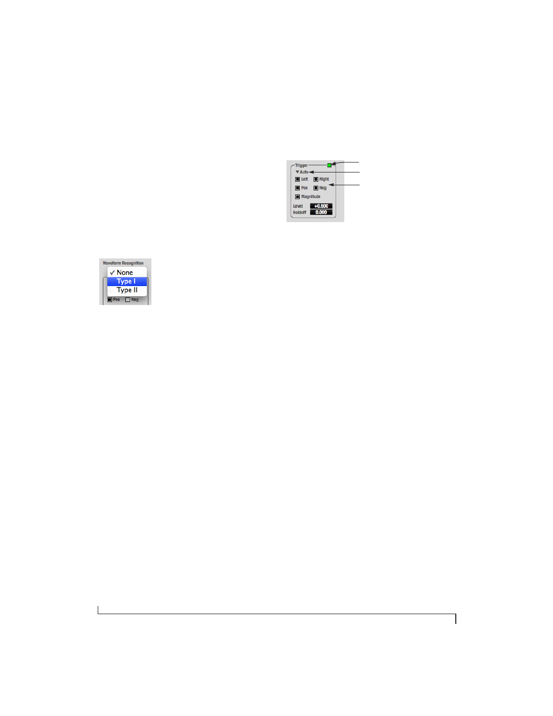
Waveform Recognition
The Waveform Recognition option searches
through new audio data looking for a waveform
which most resembles that which was previously
displayed. The region where this takes place is a
small window around the line marking time equals
zero, denoted by the extra vertical graph lines
surrounding it. There are two kinds of waveform
recognition available: Type I and Type II.
Figure 10-36: Waveform Recognition menu
Type I recognition provides the most stable display
of the waveform. It is the most resistant to change.
Louder transients, such as those produced by a
snare drum, are not displayed inside of the
waveform window. Type I is best for observing the
shape of a signal produced by a synthesizer or
observing the tone of a guitar through a chain of
pedals.
Type II recognition is less resistant to change. It will
include loud transients within the waveform
recognition window. Type II is better for observing
percussive music where the beat itself is to be
centered within the waveform window.
Trigger
When the
Trigger
(Figure 10-37) is not enabled
(the Trigger menu is set to
None
), the graph
updates based on time: after every
n
samples of the
monitored audio signal, the most recent samples
are displayed. When the Trigger is enabled (set to
any mode other than
None
), the graph updates in
response to specific conditions in the signal. The
Trigger section defines that criteria and how the
graph will display the events that match.
Figure 10-37: Trigger settings
Criteria
The criteria check boxes (Figure 10-37) determine
the conditions that the trigger is looking for and
where it will look for them.
The
Left
check box causes the condition to be
looked for in the left channel of the signal; likewise,
the
Right
check box looks for the condition in the
right channel. One or both of these can be enabled
simultaneously. If neither is enabled, the criteria
will not be found because the trigger is not looking
at any audio signal.
The
Pos
and
Neg
check boxes determine the slope
of the event. When the
Pos
check box is enabled,
the trigger will look for an event where amplitude is
increasing; likewise, enabling the
Neg
check box
tells the trigger to look for an event where
amplitude is decreasing. One or both of these can
be enabled simultaneously. If neither is enabled,
the criteria will not be found because the trigger is
not looking for any particular kind of event.
The
Level
setting defines the amplitude threshold
that the trigger is looking for. The Level is indicated
on the graph by a blue horizontal line (or two blue
horizontal lines, if
Magnitude
is enabled). Events
which cross this threshold using the enabled
slope(s) in the enabled channel(s) will activate the
trigger. The response of the trigger is set by the
Trigger mode (see “Trigger modes”, below).
Trigger indicator
Trigger menu
Criteria check boxes