Inferring registers using hdl code – Altera Designing With Low-Level Primitives User Manual
Page 14
1–8
Altera Corporation
Designing with Low-Level Primitives User Guide
April 2007
Low-Level Primitive Examples
Inferring Registers Using HDL Code
To make the most efficient use of the signals in the device, your HDL code
should match the device architecture as closely as possible. Because of the
layout of the architecture, the control signals have a certain priority.
Therefore, your HDL code should follow that priority whenever possible.
If you do not follow the signal priority, your synthesis tool emulates the
control signals using additional logic resources. Therefore, creating
functionally correct results is always possible. However, if your design
requirements are flexible (in terms of which control signals are used and
in what priority), you can match your design to the target device
architecture to achieve the optimal performance and logic utilization
results.
There are certain cases where using extra logic resources to emulate
control signals can have an unintended impact. For example, a
clock
_
enable signal has priority over a synchronous
_
reset or a
clear signal in the device architecture. The clock
_
enable signal
disables the clock line in the logic array block (LAB), and the
sclr signal
is synchronous. In the device architecture, the synchronous clear takes
effect only when a clock edge occurs.
If you code a register with a
synchronous clear signal that has
priority over a
clock enable signal, the software must emulate the
clock enable functionality using data inputs to the registers. Because the
signal does not use the
clock enable port of a register, you cannot
apply a Clock Enable Multicycle constraint. In this case, following the
priority of signals available in the device is clearly the best choice for the
priority of these control signals because using a different priority causes
unexpected results with an assignment to the
clock enable signal.
The signal order is the same for all Altera device families, although, as
mentioned earlier, not all device families provide every signal. In general,
use the signal order shown in
.
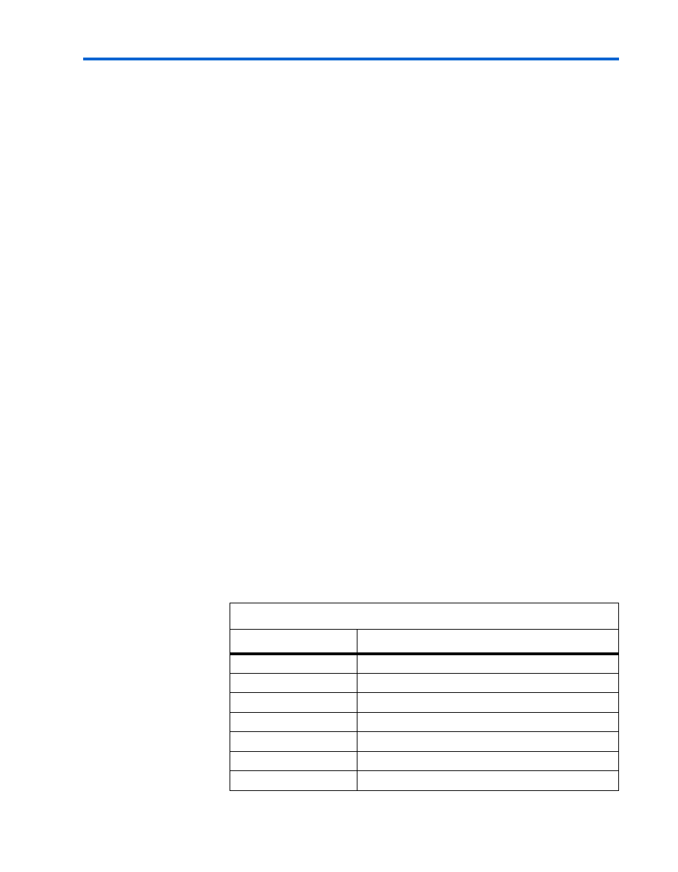
Table 1–1. Signal Order (from Highest to Lowest Priority)
Priority
Signal
1
Asynchronous clear
2
Preset
3
Asynchronous load
4
Enable
5
Synchronous clear
6
Synchronous load
7
Data in