Altera Nios Development Board User Manual
Page 24
2–16
Altera
Corporation
Nios Development Board Reference Manual, Stratix II Edition
July 2005
Expansion Prototype Connectors (PROTO1 & PROTO2)
■
A logic-negative power-on reset signal.
■
Five regulated 3.3V power-supply pins (2A total max load for both
PROTO1 & PROTO2).
■
One regulated 5V power-supply pin (1A total max load for both
PROTO1 & PROTO2).
■
Numerous ground connections.
The PROTO1 expansion prototype connector shares Stratix II I/O pins
with the CompactFlash connector (CON3). Designs may use either the
PROTO1 connector or the CompactFlash connector.
f
Refer to the Altera web site for a list of available expansion daughter
cards that can be used with the Nios development board at
www.altera.com/devkits.
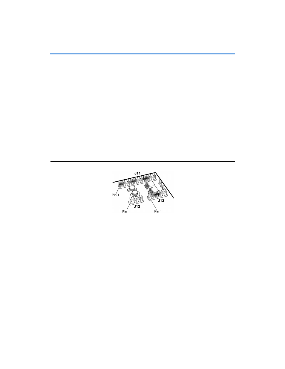
, and
show connections from the
PROTO1 expansion headers to the Stratix II device. Unless otherwise
noted, labels indicate Stratix II device pin numbers.
Figure 2–7. PROTO1 Expansion Prototype Connector - J11, J12 & J13