Mictor connector (j25), Mictor connector (j25) –22 – Altera Nios Development Board User Manual
Page 31
Altera Corporation
2–23
July 2005
Nios Development Board Reference Manual, Stratix II Edition
Board Components
Mictor
Connector (J25)
The Mictor connector (J25) can be used to transmit up to 27 high-speed
I/O signals with very low noise via a shielded Mictor cable. J25 is used as
a debug port. Twenty five of the Mictor connector signals are used as data,
and two signals are used as clock input and clock output.
Most pins on J25 connect to I/O pins on the Stratix II device (U60). For
systems that do not use the Mictor connector for debugging the Nios II
processor, any on-chip signals can be routed to I/O pins and probed at J25
via a Mictor cable. External scopes and logic analyzers can connect to J25
and analyze a large number of signals simultaneously.
f
For details on Nios II debugging products that use the Mictor connector,
refer to www.altera.com.
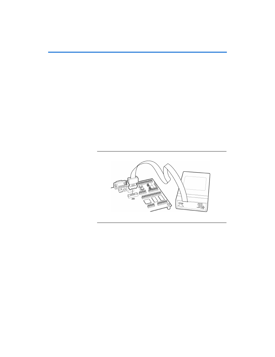
shows an example of an in-target system analyzer ISA-
Nios/T (sold separately) by First Silicon Solutions (FS2) Inc. connected to
the Mictor connector. For details see www.fs2.com.
Figure 2–12. An ISA-Nios/T Connecting to the Mictor Connector (J25)
Five
of the signals connect to both the JTAG pins on the Stratix II device
(U60), and the Stratix II device’s JTAG connector (J24). The JTAG signals
have special usage requirements. You cannot use J25 and J24 at the same
time.
below shows connections from the Mictor connector to the
shows the pin out for J25. Unless otherwise
noted, labels indicate Stratix II device pin numbers.