Monroe Electronics Electrostatic Fieldmeter - Static Monitor - model 177A User Manual
Page 10
Advertising
9
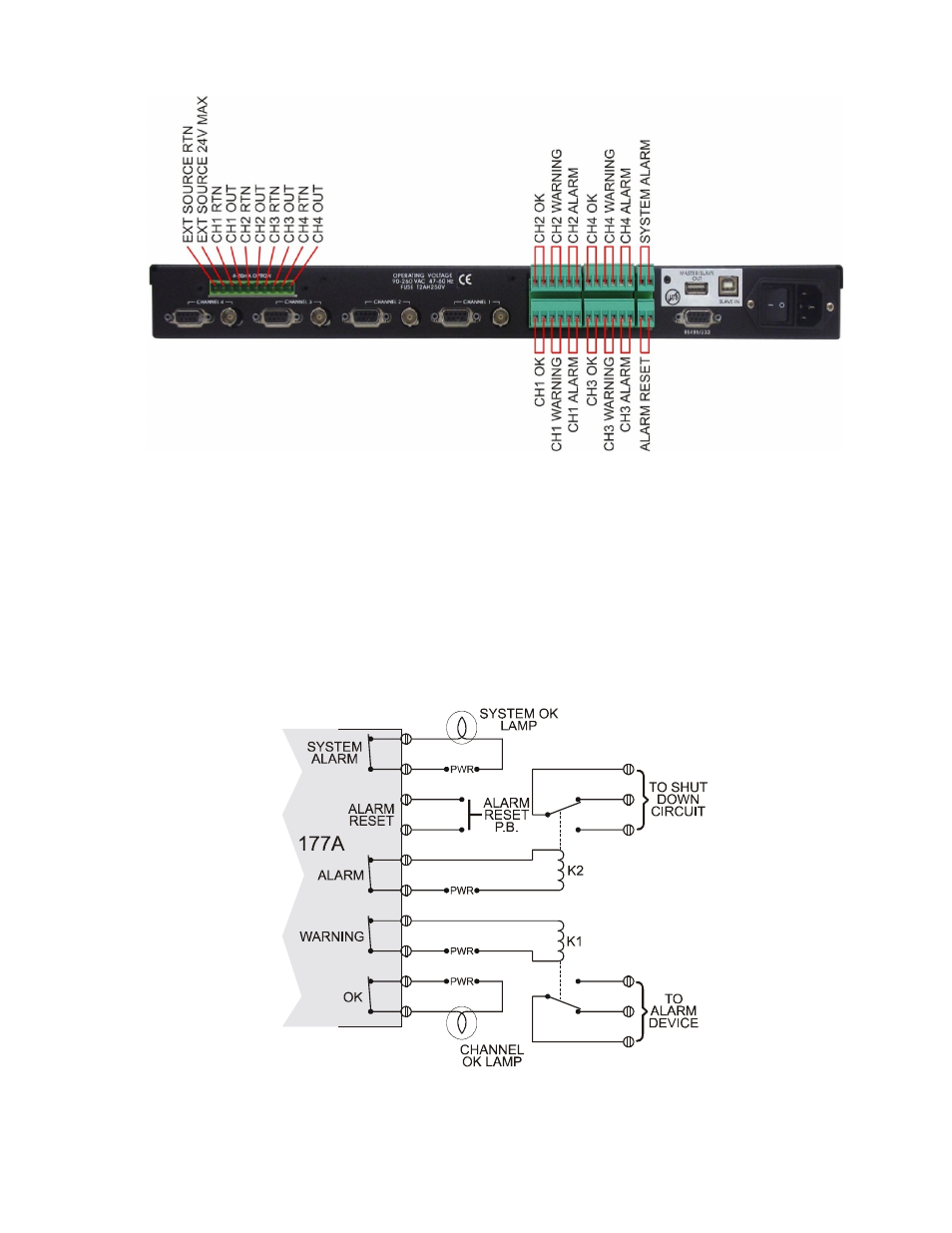
Rear panel alarm relay connections:
Three status LEDs and relays are assigned to each channel. These LEDs and relays are referenced
as OK, WARNING, and ALARM. External monitoring equipment can be connected to these relays
and indicator LEDs via screw terminals located on the rear panel of the instrument and assigned as
specified on the instruments cover.
Connections should be made using the following diagram as a guide. For operational information
refer to the Rear Panel Relay Connection segment in Section 8 of this manual.
Input
Figure 8: Rear Panel Relay Connections
Figure 7: Rear panel relay hookups
Advertising