1036 probe assembly – Monroe Electronics Electrostatic Fieldmeter - Static Monitor - model 177A User Manual
Page 84
APNE-0016
83
Standardization
A simple, accurate means of standardizing Model 1036 probes using any channel of the
Model 177A Static Monitor is given here.
The primary reason for standardization of Model 1036 probes is to assure interchangeability
of probes. The procedure is not suggested as routine, but is presented here in the event it
becomes necessary to re-standardize following replacement of a gradient cap or major
probe overhaul. It should be performed only under controlled conditions in a suitably
equipped electronics laboratory.
All Model 1036 probes are shipped from the factory standardized in a uniform (parallel) field.
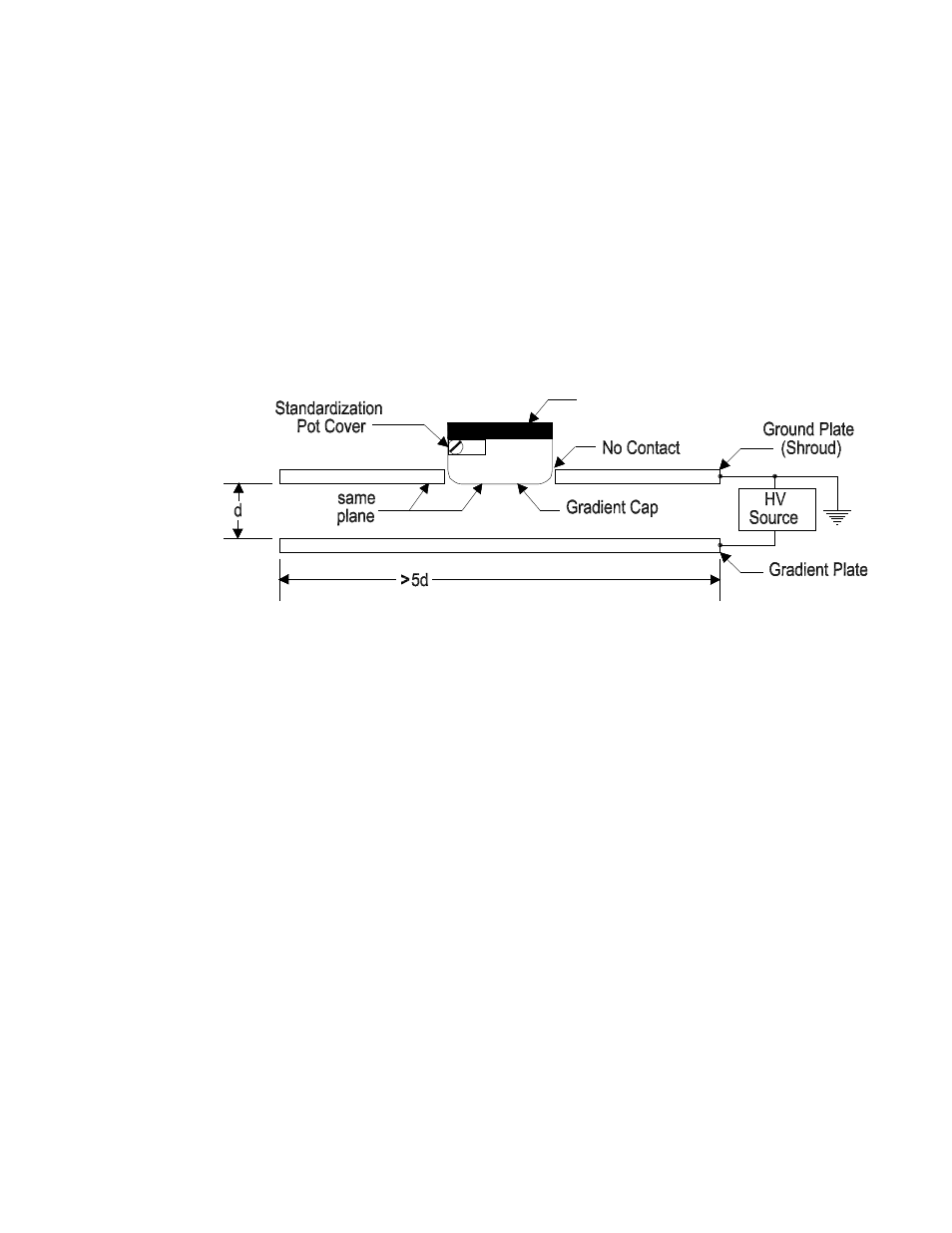
The calibration fixture consists of two flat rigid metal plates that are parallel and separated
with insulators by a distance "d" of one inch and have side dimensions of at least 5d (the
bigger, the better; within practical limitations). Refer to Figure II-2 for a description of this
fixture and the calibration method.
Figure II-2
Standardization Fixture (P.N. 96102A) Setup for 1036 Probes
The ground plate has a hole in its center just large enough to provide clearance around the
probe so that the probe does not make contact with the plate. A calibrating voltage is applied
to the gradient plate of the fixture to establish a reference field in the volume between the
plates. This fixture is available from Monroe Electronics, Inc. as part number 96102A.
A Probe Standardization/Test Cable, Monroe Electronics model number 1036/22C, is
required to standardize or bench-test Model 1036E probes. No special cable is required for
Model 1036F probes.
The standardization procedure is as follows:
Set up the apparatus as outlined above. Set a precision calibrating voltage source
to zero volts.
Set the Model 177A Static Monitor zero control of the selected channel to read a
value of 0.000 at its analog output using a high-quality digital multimeter (DMM).
Table II-2 lists the precision high voltage (V
HV
) source requirements for
standardization of the various probes. Apply the calibrating source voltage (V
HV
),
as shown in Table II-2, for the probe model being calibrated.
Adjust the calibration potentiometer in the probe to produce value (V
IND
), as
shown in Table II-2, at the analog output of the selected channel using the same
DMM as above.
1036 Probe
Assembly