Monroe Electronics Electrostatic Fieldmeter - Static Monitor - model 177A User Manual
Page 51
50
Application Note APNE-0003
Fieldmeter Measurement Techniques Using Monroe
Electronics Model 1036 Probes
Monroe Electronics Model 1036 fieldmeter probes are calibrated (or, more correctly, "standardized") in a true
uniform or homogeneous field. The calibration fixtures used are designed to produce parallel field lines.
As a true uniform field does not usually occur in most practical measurement situations, partly due to the
introduction of the grounded probe itself, one must either:
1. Attempt to better the geometry by establishing a grounded plane, through which the fieldmeter probe
can view the field under consideration,
2. Establish a correction factor for the data, or
3. Accept relative data. In many cases, this is perfectly acceptable practice once a fixed geometry is
established.
Some guidelines are offered here.
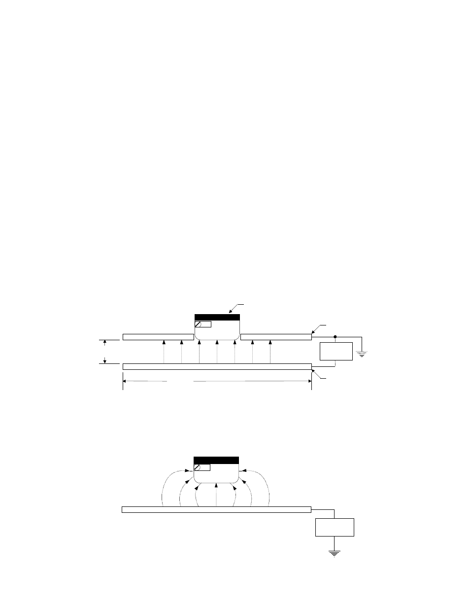
During the standardization procedure, these probes are configured as shown in Figure 15 with the face of the
probe flush with the bottom of the upper metal plate or "shroud" which is referenced at ground potential. This
shroud effectively increases the area of the face of the probe. It and the surface under test (in this case, gradient
plate) can be considered to be infinitely large as long as the size of the plates exceeds 5 or 6 times the distance
between the plates.
Please note that the diameter of the face of the Model 1036F probe is approximately 1½ inches. The face of the
Model 1036E is 4¼ inches by 2¾ inches. Either probe type used on its own without a shroud will tend to perturb
a field as shown in Figure 16.
HV
Source
Convergent field lines
Figure 16
1036 Probe
Ground
Plate
Gradient
Plate
d
>
5d
HV
Source
(Shroud)
Figure 15