Monroe Electronics Electrostatic Fieldmeter - Static Monitor - model 177A User Manual
Page 81
APNE-0016
80
Installation
Sensitivity
Full-scale sensitivity for any properly standardized and calibrated probe/instrument
combination is dependent upon the gradient cap (containing the aperture) on each probe.
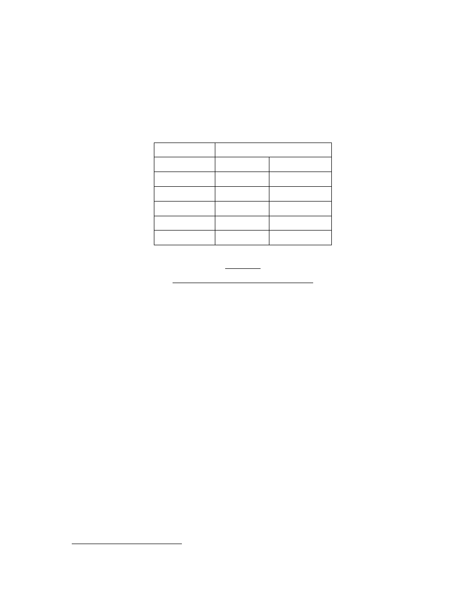
The full-scale sensitivity for any given fieldmeter system or channel can be determined by
inspecting the gradient cap on the probe. Each gradient cap is stamped on its face with a
number that represents a different size aperture. This number is related to the sensitivity of
the probe as shown in Table II-1 below. The probes are standardized at the factory in a
uniform electric field. Once standardized in this manner, they may be interchanged at will.
Probe Model
Full Scale Sensitivity
1036_-2
±100 V/cm
(±10 kV/M)
1036_-3
±1 kV/cm
(±100 kV/M)
1036_-4
±10 kV/cm
(±1 MV/M)
1036_-5
±20 kV/cm
(±2 MV/M)
1036_-6●
±10 kV/in
Standard
1036_-7
±1 kV/in
Table II-1
Probe Model vs. Full Scale Sensitivity
Mounting
Probe mounting requirements for electrostatic field measurements will vary somewhat with
the nature of the desired measurement. Whenever possible, mount the metric-reading
probes from Table II-1 at one centimeter and the English-reading probes at one inch. When
this is not possible, it is best to mount the probe as near as practical to the surface being
monitored, as long as the input signal remains less than the full-scale sensitivity of the
probe. It is strongly recommended that the probe be mounted "looking" downward in order to
minimize the probability of contaminants entering the aperture in the face.
Model 1036E is provided with two mounting flanges that accommodate ¼” bolts or screws.
The case should be electrically connected to ground. The gradient cap (containing the
aperture) of the probe is a reference surface with its own ground connection. Do not make a
separate ground connection to this surface.
Model 1036F may be held by hand to make rough measurements, or mounted by means of
two threaded inserts in the back plate of the probe. Care must be exercised when selecting
screw length. These are blind holes with a depth of 0.089". They will accommodate up to five
full #4-40 threads. Some additional, temporary mounting options are friction clamps,
adhesives, or double-sided tape. The metal body of the probe is internally connected to
instrument ground and should not normally be connected to any other ground.
Geometry
A shroud
5
is not necessary on 1036E probes mounted at one inch or less from the web
because the large faceplate provides the same function as a shroud (creates a uniform
electric field in front of the probe at one inch or less). For more information about shrouds,
see Application Note APNE-0003 Fieldmeter Measurement Techniques Using Monroe
Electronics Model 1036 Probes.
5
A shroud in this instance is a grounded surface in the plane of the gradient cap. For more information about
shrouds, see Application Note APNE-0003 Fieldmeter Measurement Techniques Using Monroe Electronics
Model 1036 Probes.