4 – 20 ma option board installation instructions – Monroe Electronics Electrostatic Fieldmeter - Static Monitor - model 177A User Manual
Page 32
31
4 – 20 ma Option Board Installation Instructions
1. Un-plug all external connections to the 177A including the power cord.
2. Remove the 7 phillips-head screws that hold the cover of on the chassis. Remove the cover
and set aside.
3. Remove the 2 screws holding the 4-20 ma option cover on the 177A back panel. Discard
these parts.
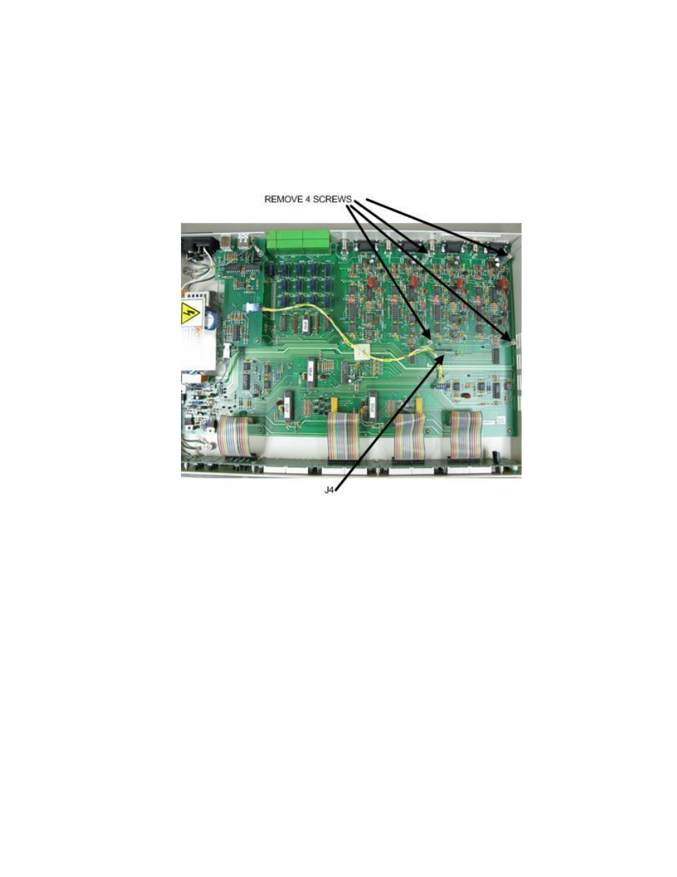
4. Remove the 4 phillips-head screws from the tops of the mounting stand-offs as shown
below.
5. Remove mating connector from 177A/22A.
6. Align the electrical connector on the 177A/22A with J4 on the 177A main board.
7. Press down and engage this connector with J4 until the board is seated on all 4 mounting
stand-offs.
8. Re-install the 4 screws removed in step 4.
9. Replace the 177A cover and re-install it’s mounting screws.
10. Installation complete. Connect the 4-20 ma outputs as shown on next page using mating
connector supplied.