Operation – Monroe Electronics Electrostatic Fieldmeter - Static Monitor - model 177A User Manual
Page 20
19
Section 8
OPERATION
Front Panel Features
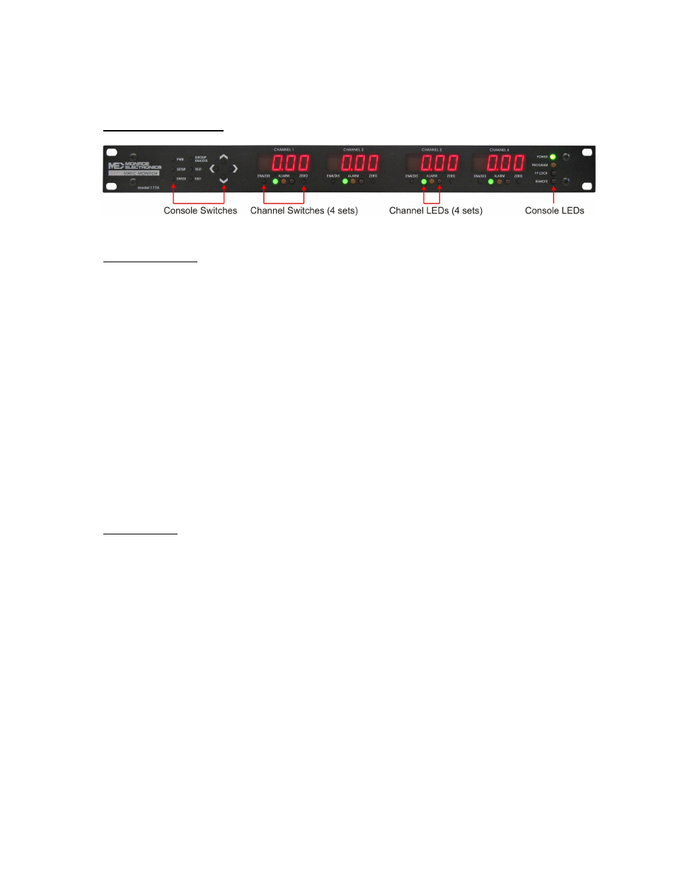
Figure 15: Front Panel View
Console Switches
PWR – Switches unit ON or OFF (There is a main power switch on the rear panel that supplies DC
power. The front panel console push button switches the power to the to the unit’s power supply.) If
line power is lost, the 177A will return to operational status when power is restored.
GROUP ENA/DIS - All channels in the group (of four) are enabled on power-up. These channels
may be immediately and simultaneously disabled by pressing the GROUP ENA/DIS button on the
front panel or clicking the GROUP ENA/DIS button on the program monitor screen.
SETUP – Initiates programming via the front panel. Yellow Program LED lights when SETUP button
is pressed and remains lit for duration that instrument is in program mode.
TEST – Initiates testing of all connected and enabled probes. Pressing and holding down the TEST
button causes a shift in the probe reading to the minus direction, the reading should return to normal
when the button is released, indicating a good probe.
ENTER – Press ENTER to accept changes during programming or to perform a function.
EXIT – Press EXIT to escape the changes or exit the program mode.
Console LEDs
POWER – Green LED lights when power is applied to the instrument. A flashing power LED
indicates a problem with the instrument’s power supplies. If this occurs refer to the
Return Policy on page 3 for servicing.
PROGRAM – Yellow LED lights when the SETUP switch is depressed and remains lit until the
program mode is exited. If master/slave units are utilized the program light will pulse
on the master unit which drives probe oscillation. If it is a slave unit the program light
will not be lit.
The program LED does not pulse when the unit is in program mode.
The program light flashes (pulses at a slower rate) when the unit is receiving a
firmware update. If the update is interrupted either, by the user or power failure, the
light will flash and remain flashing until the update is completed successfully.
FP LOCK – Red LED indicates that the front panels controls have been locked. When locked the
front panel buttons do not function except for Power, Setup and Exit. FP lock can be
enabled or disabled via the front panel controls or the pc software supplied.
REMOTE – Lights when the PC program is in use.