Monroe Electronics Electrostatic Fieldmeter - Static Monitor - model 177A User Manual
Page 46
45
Setup Station ID (continue from above):
Press Key
Display(blinking)
Display Description
Left
IT
Interface Type
Down
Sn
Station number
Right
001
Enter station ID
Enter
Setup RS-485 from ME177A software: Connect the 177A unit to the PC’s comport. On the main entries screen,
click on Get – Active Program. This leads to Program Setup screen. Click on [Hardware Config] button to go to
the System Setup Screen. Enter the Station ID, Select Serial Type and Terminator. Click the [Send & Exit]
RS-232 To RS-485 Converters:
When connecting to the PC’s comport, an RS-232 to RS-485 converter may be needed (see Diagram above).
When connecting to the PC’s USB port, an USB to RS-485 converter is needed (see Diagram above). The
following device has been tested to use with 177A: VScom USB-COMi Adapter.
Connection to the 177A: Locate the DB-9 connecter on the back of the unit, connect the two wires to the 485
data as follows:
RS-485Bus
177A DB-9
Data+
Pin3
Data-
Pin2
For correct operation of the transmitter and the receiver, a return signal path between the grounding of individual
devices is required. It may be realized either by a third wire, or by grounding each device (third pole in the mains
socket).
Cable Selection For RS-485 Systems
Category 5 cable is available as shielded twisted pair (STP) as well as unshielded twisted pair (UTP) and
generally exceeds the recommendations for RS-422 making it an excellent choice for RS-485 systems
Setup for the Station ID and Terminator is the same as setup RS-485 Half, see above for details.
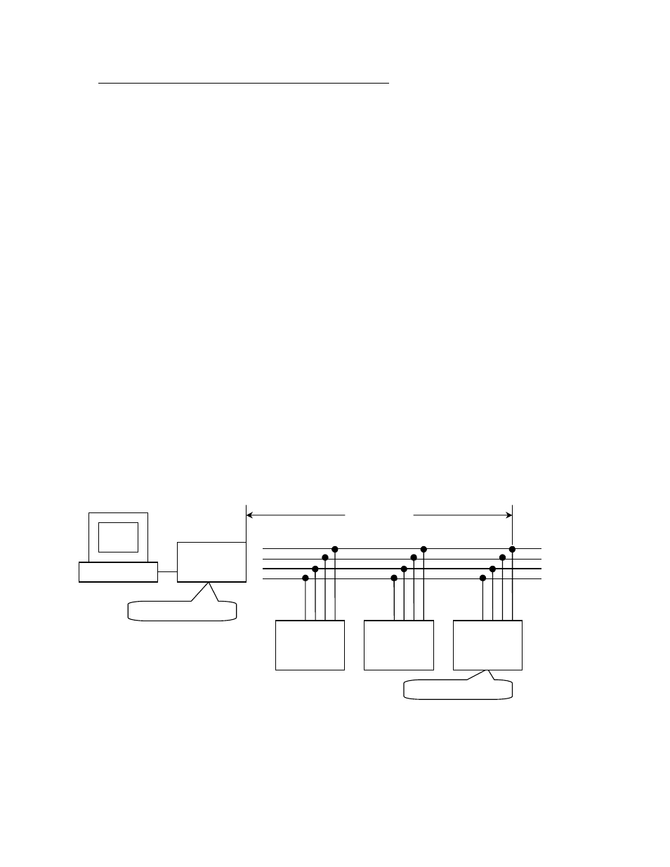
RS-485 Full Duplex (RS-422)
Termination enables
Termination enables
Up to 4000 feet
Pin1 9 2 3
177A
Unit 1
R+
R-
T+
T-
R+
R-
T+
T-
RS-232 or USB
to RS-485
Converter
Pin1 9 2 3
177A
Unit 2
Pin1 9 2 3
177A
Unit n