Iii. principle of operation – Monroe Electronics Electrostatic Fieldmeter - Static Monitor - model 177A User Manual
Page 86
APNE-0016
85
III.
Principle of Operation
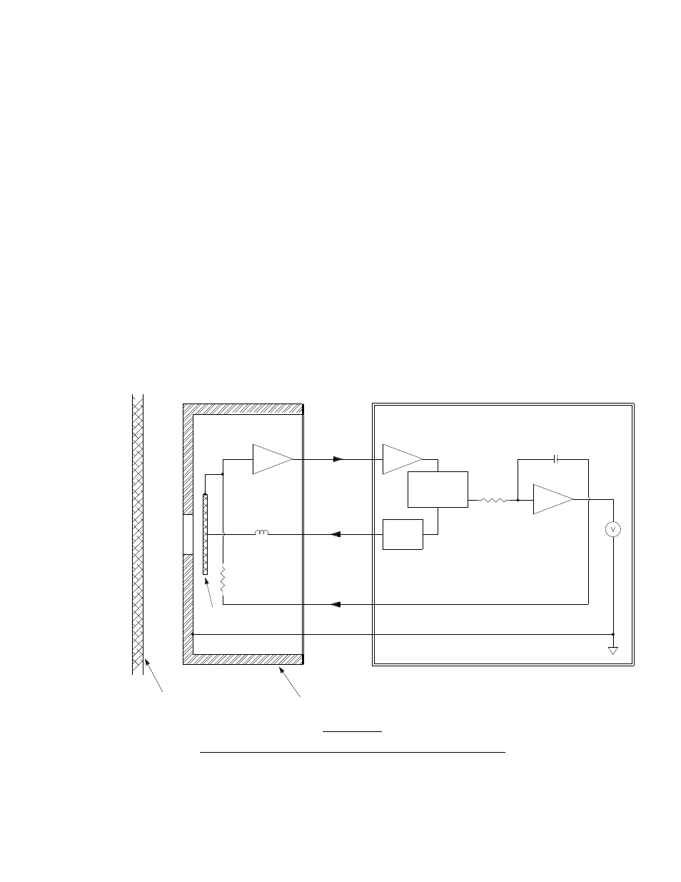
Refer to Figure III-1 for the following discussion.
The probe is placed to “view” the target surface, which is assumed to be charged. In this instance,
the gradient cap containing the aperture faces the target surface.
A sensitive electrode behind the aperture is vibrated perpendicular to the electric field by means of a
drive coil (vibrated toward and away from the target surface). An A.C. signal is induced onto the
sensitive electrode due to the motion of the vibrating electrode in the electric field, which is created
by the charges on the target surface. The modulation amplitude of the A.C. signal, relative to the
drive coil signal, is related to the polarity of the charge on the target surface.
This A.C. signal, conditioned by a preamplifier, filter, and signal amplifier, is fed into a phase-
sensitive demodulator. This signal from this demodulator feeds an integrating amplifier. A fraction of
the integrator’s output signal is fed back to the sensing electrode to null the signal from the external
electric field.
The voltage signal from the integrator is thus directly proportional to the field intensity at the sensing
electrode of the probe. The output signal from the integrator drives a meter for direct readout.
The fieldmeter gives a reading of the field intensity at any spacing. If the spacing is known, the
voltage on the target surface can be determined.
Figure III-1
Simplified Block Diagram for an Electrostatic Fieldmeter
Phase
Sensitive
Demodulator
Signal
Amplifier
Reference
Oscillator
Integrator
Voltmeter
High Input Impedence
Preamplifier
Signal
Reference
Feedback
Surface Under Test
Gradient Cap (Probe Housing)
Sized Hole
(Aperature)
Vibrating
Electrode
Main Meter Assembly
Probe
Driving Coil