Typical setup – Monroe Electronics Electrostatic Fieldmeter - Static Monitor - model 177A User Manual
Page 19
18
Section 7
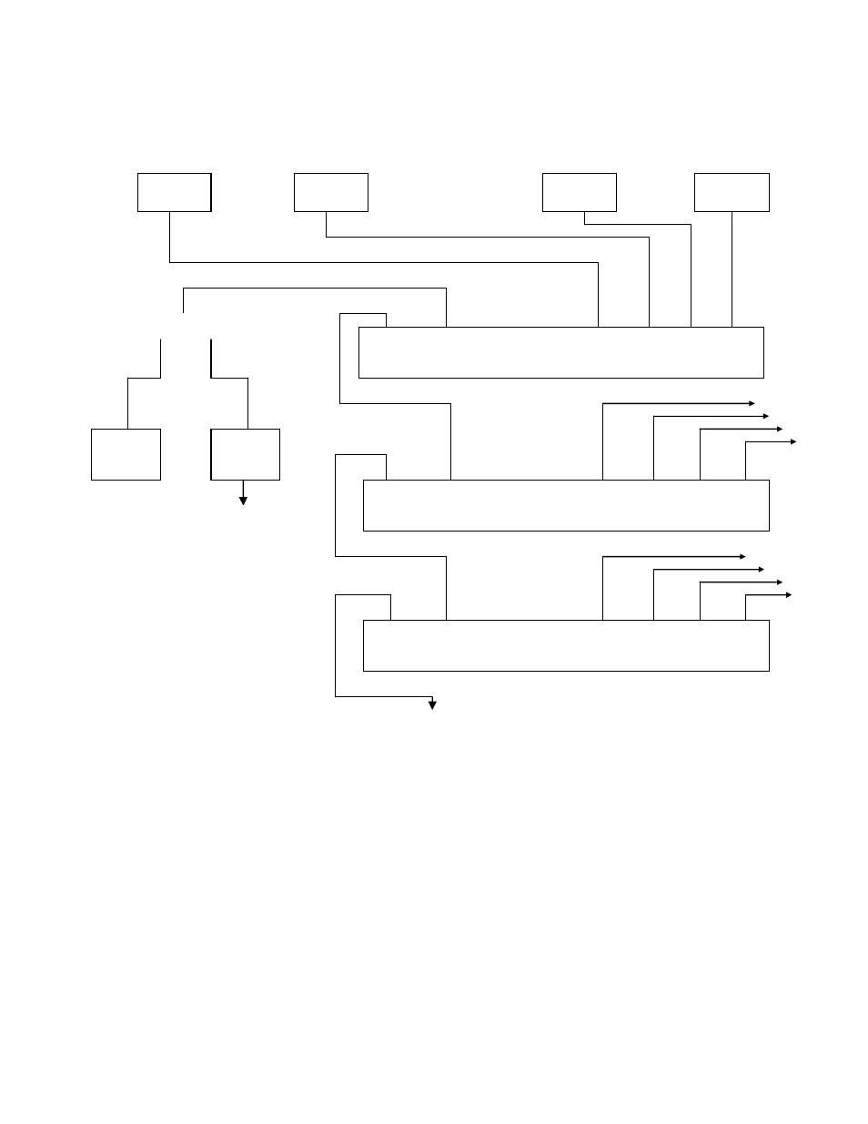
Typical Setup
Analog Inputs
Monitoring equipment for voltage levels may be connected to any or all of the for channels via the
BNC connectors located adjacent to each channel probe connector on the rear panel on the
instrument.
Monitoring equipment for current levels may be connected to the optional 4-20mA pcb via screw
terminals located on the rear panel of the instrument.
To 1036
Sensors
9-12
To 1036
Sensors
5-8
1036
Sensor
#2
1036
Sensor
#4
1036
Sensor
#3
1036
Sensor #1
Master RS-485 /232
1 2 3 4
Slave/Out
177A Master
RS-232
PC
Master Slave In
1 2 3 4
Slave/Out
177A #2 Slave
Master Slave In
1 2 3 4
Slave/Out
177A #3 Slave
Figure 14 – Block Diagram of a typical set up
RS-485
PLC
to a PC or PLC
Analog out