Basler Electric BE1-11 IEC 61850 Protocol User Manual
Page 13
9424200892 Rev F
7
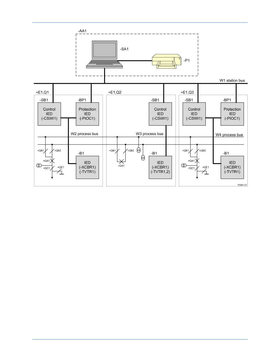
Figure 4. Configuration Example (from IEC 61850-6)
The IEC 61850 standard is based on the hierarchical addressing and information model in a station. It
follows, in this way, the structure of the substation equipment independent of IED structure and
organization. This information and addressing model is also visible in the IEC 61850 telegrams because
the address is presented in MMS (Manufacturing Message Specification) as an ASCII string, so the
address can be seen directly in a readable form.
The IEC 61850 standard defines the information and its exchange in a way that it is independent of a
concrete implementation (i.e., it uses abstract models). The standard also uses the concept of
virtualization. Virtualization provides a view of those aspects of a real device that are of interest for the
information exchange with other devices. Only those details that are required to provide interoperability of
devices are defined in the IEC 61850 standard.
The approach of the standard is to decompose the application functions into the smallest entities, which
are used to exchange information. These entities are called logical nodes (for example, a virtual
representation of a circuit breaker class, with the standardized class name XCBR). Several logical nodes
build a logical device (for example, a representation of a Bay unit). A logical device is always
implemented in one IED; therefore logical devices are not distributed.
Real devices on the right-hand side of Figure 5 are modeled as a virtual model in the middle of the figure.
The logical nodes defined in the logical device (for example, Bay) correspond to well-known functions in
the real devices. In this example, the logical node XCBR represents a specific circuit breaker of the bay to
the right.
BE1-11
IEC 61850 Engineering