Basler Electric BE1-11 IEC 61850 Protocol User Manual
Page 19
9424200892 Rev F
13
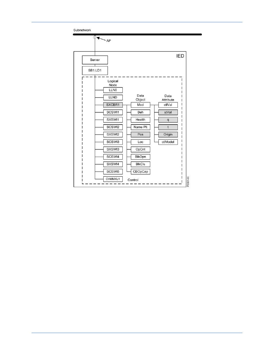
Figure 11. Organization of LDs, LNs, DOs, and DAs in an IED
An IED server represents the communication interface to the sub network (Ethernet).
•
One or more Logical device(s) are connected to a server
•
A set of Logical Nodes belong to a Logical Device
•
The Logic Node LLN0 is a special Logic Node per Logic Device and contains the DataSets,
GOOSE Control Blocks (GoCB), Report Control Blocks (RCB), and Setting Group Control Block
(SGCB)
•
The Logic Node LPHD is a special Logic Node per Logic Device and contains Data Objects (DO)
which describe the status of the physical device (the IED)
•
Each Logical Node represents a function and contains a number of Data Objects (DO)
•
Each DO is represented by a number of Data Attributes (DA)
The data objects are representing information signals which may be routed to station level IEDs.
The signal engineering task is to select the requested signals (DOs) and link them to the client IEDs as
receiver. The control services are not directly engineered. They are included in the data objects which
handle both directions the command (control) and the response (monitoring). When routing the DO in
monitoring direction the control is known by the clients. The organization of the IED from LD down to DAs
can be viewed in the BEST61850 tool. This organization concept must be taken into consideration when
DataSets are configured.
The number of data objects and data attributes per Logical Node is defined by the used LN type in this
IED. The contents are taken from the Data Type Templates which belong to an IED type.
BE1-11
IEC 61850 Engineering