Inserting the fold plates and the deflectors – MBM Corporation 352S User Manual
Page 36
Operator's Manual
multipli 35
Buckle Fold Unit 35/2 and 35/4
Mathias Bäuerle GmbH
39
Inserting the Fold
Plates and the
Deflectors
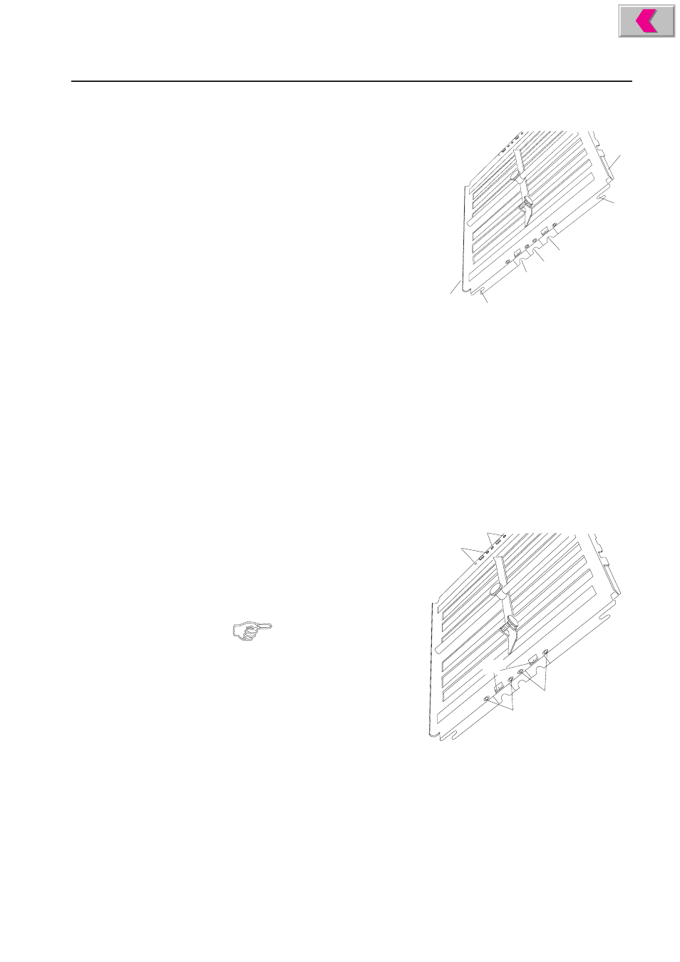
The fold plates must be inserted in such a
way
that two cutouts each (1, 2, 3, 4, 5) engage in
the positioning pins which are located in the
side panels of the fold unit.
Proceed as follows:
•
Guide the fold plates with the mouth
pointing forward (6) between the side
panels of the fold unit.
Cutouts (1) and (2) must engage in the
positioning pins on the left- and right-
hand side.
•
If a fold plate is to be used as deflector, turn it by 180° and slide it between the
side panels with the uninterrupted surface (7) pointing forward. Cutouts (4) and
(5) must engage in the positioning pins on the left- and right-hand side.
•
Check whether all pins are firmly engaged by turning the fold rollers by the
handwheel.
•
Cutout (3) is for inserting fold plates in machines which were built before
March 1997. (Up to that date, the positioning pins were in different positions).
Displacing the Fold Plates and Deflectors
There are special adjustment devices (8, 9) at the left- and right-hand side of the fold
plates which make it possible to reduce the distance to the fold rollers, for example,
when folding thin paper.
•
Loosen the Allen screws on both
sides of the fold plate (2.5 mm
wrench).
1
2
3
4
5
6
7
10
8
9
9
8
Set all 4 adjustment devices to
the same measurement to make
sure that the fold plate always
has the same distance to the
fold rollers, no matter whether
it is used as fold plate or as
deflector.
•
Retighten the Allen screws.