Peak meter, Gain reduction meter, Peak, rms, vu output meter – Metric Halo Production Bundle User Manual
Page 38: 38 gain reduction meter, 38 peak, rms, vu output meter, 38 8.22. gain reduction meter, 38 8.23. output meter, Advanced metering, Scalable gain reduction meters
Operation
38
ChannelStrip also uses a number of standard visual representations to give you feedback about what is hap-
pening within the processor. These elements are:
Peak Meter
Figure 8.21: Peak Meter
ChannelStrip provides a peak-reading meter at the input stage of each processing block. The meter uses the
fast PPM standard for decay time (0.9 seconds per 20 dB) and the digital PPM standard legend for calibration.
On the dynamics sections (gate and compressor) a white bar is visible on top of the meter and indicates the
current detector level. For the dynamics sections the processor threshold is indicated by the red slider over the
input peak meter. This slider can be manipulated directly with the mouse. The top segment of the meter (above
0dB) is used as a clip indicator and is illuminated red if the input section of the processor detects an over.
The clip light remains illuminated until you click on the meter. Mac
⌥ (Option)–click or Windows Alt-click
any meter to reset the clip lights on all of the meters in ChannelStrip. When ChannelStrip is running in stereo
mode, this meter shows the higher of the two input levels and will detect an over on either input channel.
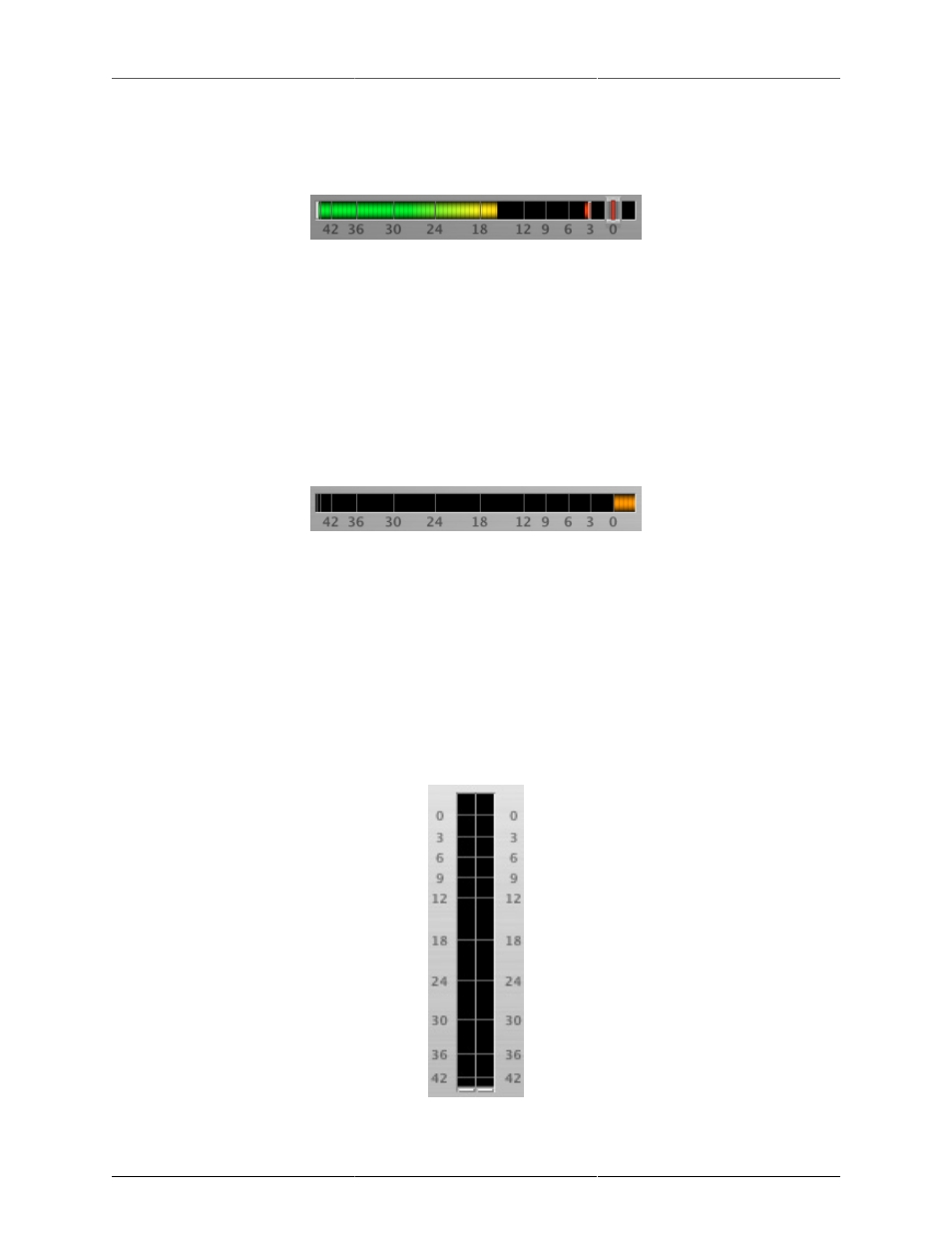
Gain Reduction Meter
Figure 8.22: Gain Reduction Meter
The gain reduction meter, which has an orange bar and grows down from 0 dB, shows the amount of attenua-
tion being applied by its associated dynamics processor at any given time. If you right-click (Mac/Win) or Mac
⌃ (Control) click on the meter, you may set the scale of the gain reduction meter to any of the following values:
• 54 dB
• 24 db
• 12 db
• 6 db
• 3 db
Peak, RMS, VU Output Meter
Figure 8.23: Output Meter