Vcm-x / rne setpoints, Vcm-x / rne setpoint screens, Vcm-x / rne operator interface sd – Orion System VCM-X/RNE Controller User Manual
Page 51
VCM-X / RNE Operator Interface SD
VCM-X / RNE SETPOINTS
51
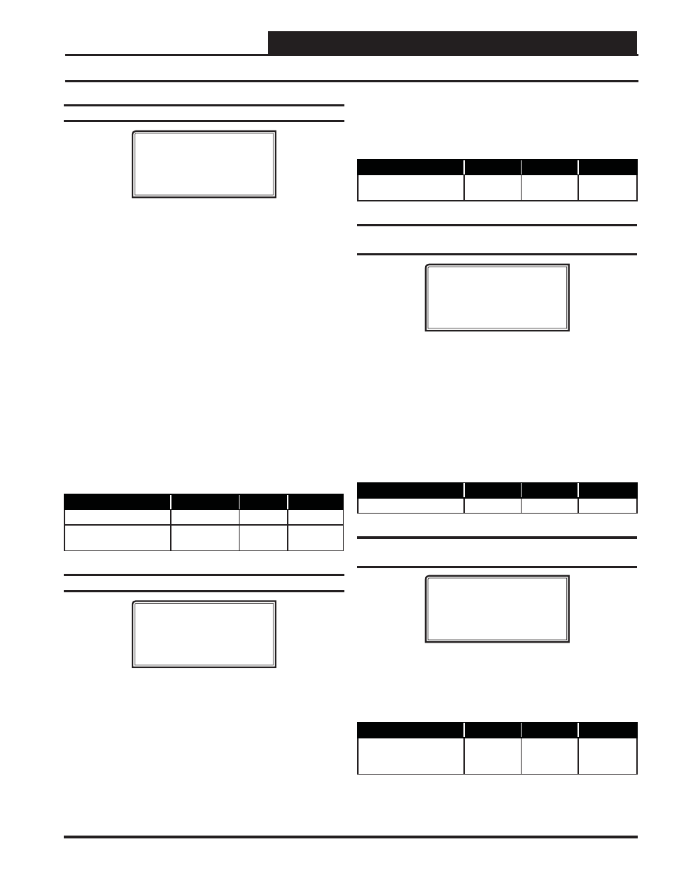
Setpoint Screen #24 - Building Pressure
VCM-X / RNE Spts
Building Pressure
Setpoint....: 0.10”
Deadband....: 0.02”
Direct Acting Control
If an Exhaust Fan Relay is confi gured, when the Building Static Pres-
sure rises above the Building Pressure Setpoint plus the Deadband, the
Exhaust Fan Relay will activate. It will remain on until the Building
Pressure falls below the Building Pressure Setpoint minus the Deadband.
If Modulating Building Pressure is confi gured, when the Building Static
Pressure rises above the Building Pressure Setpoint plus the Deadband,
the Building Pressure Output Signal will increase until the Building Static
Pressure falls within the Deadband. If the Building Static Pressure falls
below the Building Pressure Setpoint minus the Deadband, the Building
Pressure Output Signal will decrease until the Building Static Pressure
rises within the Deadband. The Building Pressure Output Signal is con-
fi gurable for 0-10 or 2-10 VDC. For more detailed operation information,
see the VCM-X Controller Technical Guide, VCM-X Modular E-BUS
Controller Technical Guide, or RNE Controller Technical Guide for the
complete Building Pressure Control Sequence of Operation.
Reverse Acting Control
The Building Pressure Output Signal remains a Direct Acting 0-10 or
2-10 VDC signal, but the logic is reversed. On a drop in Building Static
Pressure below the Building Pressure Setpoint minus the Deadband, the
Building Pressure Output Signal will increase.
Description
Min.
Default
Max.
Building Pressure Spt
-0.20″ WG
0.10″ WG
0.20″ WG
Building Pressure
Deadband
0.01″ WG
0.02″ WG
0.10″ WG
Setpoint Screen #25 - RAB Damper Factor
VCM-X / RNE Spts
Return Air Bypass
Damper Factor
Setpoint..: 40%
This setpoint is used when your HVAC unit is confi gured for Return
Air Bypass Damper control. The Return Air Bypass Damper Factor
Setpoint is a percentage value that is used to calculate the Return Air
Damper position in relation to the Return Air Bypass Damper position.
This provides a method for adjusting the airfl ow through the Return
Air Bypass Damper.
Increasing this percentage increases the airfl ow through the Return Air
Bypass Damper by causing the Return Air Damper to move further
towards its closed position in relation to the Return Air Bypass Damper
moving towards its open position.
Decreasing this percentage decreases the airfl ow through the Return
Air Bypass Damper by causing the Return Air Damper to move further
towards its open position in relation to the Return Air Bypass Damper
moving towards its closed position.
Description
Minimum
Default
Maximum
Return Air Bypass
Damper Factor
0%
40%
100%
Setpoint Screen #26 - Supply Fan Starting
Delay Timer
VCM-X / RNE Spts
Fan Starting Delay
Timer...: 255 s
This is the Supply Fan Starting Delay Timer initiated whenever the
Unit Controller initiates Supply Fan operation. This is useful when you
are using multiple HVAC units and want to be sure that all the units do
not start at exactly the same time when the Occupied schedule occurs.
Each Unit Controller should be set with staggered Fan Starting Delay
Timer Setpoint values. When the 255 Second default setpoint is used,
it multiplies each Unit Controller’s address by 5 and uses this value in
seconds as the Fan Starting Delay Time. This provides a staggered start
for each Unit Controller on the system without having to individually
set each Unit Controller for its own time delay. For an MUA unit, this
should be set to a minimum of 60 seconds to let the OA Damper open.
Description
Minimum
Default
Maximum
Fan Start Delay Timer
0 Sec
255 Sec
255 Sec
Setpoint Screen #27 - Mechanical Heat/Cool
Failure Time Period
VCM-X / RNE Spts
Mechanical Heat/Cool
Failures Occur After
No Change In 15 Min
When Heating or Cooling Mode is initiated and staging is activated, if the
Supply Air Temperature does not rise or fall 5°F within the Mechanical
Heat/Cool Failures Occur After No Change For Setpoint time period,
a Mechanical Heating or Cooling failure alarm will be generated. The
Alarm is for Status Reporting only. The HVAC unit will continue to run.
Description
Minimum
Default
Maximum
Mechanical Heat/Cool
Failures Occur After
No Change For
0 Min
15 Min
255 Min
VCM-X / RNE Setpoint Screens