Pacific Research Solutions RI-200 User Manual
Page 16
Pacific Research Solutions
RI-200 User Manual
Page 15
2.8
CONNECTING TWO RI-200 REPEATER CONTROLLERS TOGETHER
You can connect two RI-200 repeater controllers together
using the auxiliary interface connector. Over this port, the
two controllers will exchange audio, PTT and command
information. The PTT and S-Command information is sent
between the two controllers as serial data. A fixed data time-
out timer is included in this protocol to protect against
accidentally keying a transmitter. If data is not received for
four seconds, the controllers will return to a normal operating
mode. The two radios may be a repeater and a link, two links,
two repeaters or a remote base.
When you have two controllers connected together, you can
clone one controller to another. See S-Command 38 mode 2.
Cloning is the process of copying the setting from one
controller to another controller.
Connect the two controllers together with the optional IC-200 interconnect cable. If you prefer to make your own cable, the
connectors at each end of the 16 conductor flat ribbon cable are “pin flipped” with respect to each other.
Reference Macro Programming Section 5.0. Command information is sent from one controller to another by writing macros
with data telling the controller to send S-Command information to another controller and not to process that S-Command
within itself. To build a macro that will process S-Commands within the local controller, follow all the normal procedures in
this manual and in the programming macro’s section 5.0. When building a macro with S-Commands that needs to be
processed by another RI-200 controller, you simply insert an “A1” before the S-Command and its data within the macro. All
data from the “A1” through the “C” S-Command separator will be sent to the second controller. Each controller in the
system will need to have its own controller number. When sending a command to another controller, all controllers with the
same controller number as the “A” number, will execute that S-Command. All “A1” controllers will respond to “A1” prefix
macro data. All “A3” assigned controllers will respond to the “A3” prefixed macro table data.
Note:
The “controller unit address” is set with S-Command 38 and can be any address 1 through 9. The default address is
1, which can be used by both controllers, when only two controllers are connected together.
To transfer serial data between controllers, S-Command 37 must be in the default state mode 1 (37 1) serial port data
transfer mode.
The RI-200 also has a digit state data mode. S-Command 37 mode 0 used when connecting to someone else’s controller. In
this mode the auxiliary interface TTL level input and output digital signals are LOW TRUE or LOW ACTIVE. The COS
input is the same as the RXD input and the PTT output is the same as TXD output.
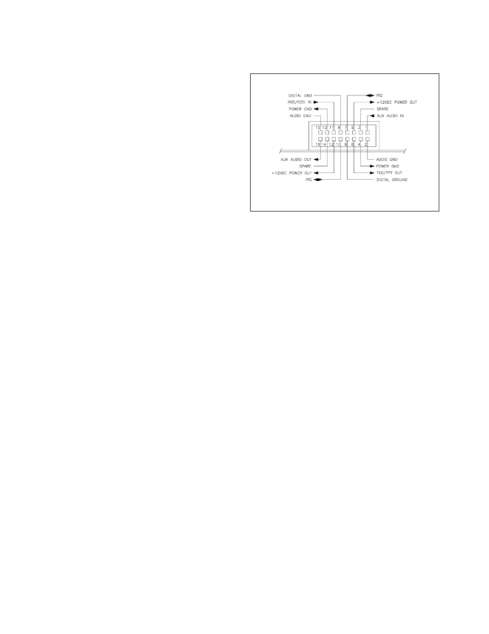
AUXILIARY INTERFACE CONNECTOR