Operating and adjusting the controller – Pacific Research Solutions RI-200 User Manual
Page 17
Pacific Research Solutions
RI-200 User Manual
Page 16
OPERATING AND ADJUSTING THE CONTROLLER
3.0
OPERATING
There are two types of control operations, user commands and system commands. The system commands or
(S-Commands) are the principle means for the repeater owner to configure and control the RI-200's basic operations. These
commands typically change the characteristics of the system or turn on/off functions of the system. The user commands are
commands that the repeater owner builds to customize the repeater for the users.
3.1
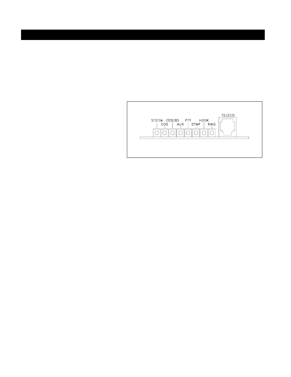
SYSTEM STATUS INDICATORS
The system status LED indicators will display the
current status of the controller. S-Command 09 is
provided to enable or disable (turn on or off) all
status LEDs. This will lower the current drain of
the controller and may be important in a solar or
portable repeater configuration. With the status
LEDs turned off, the controller will draw less than
60 ma. During the controller power on self-test,
the RI-200 will turn on all of the status LEDs for 1
second. The status display also doubles as a
receive level audiometer. When you press the
“INIT” button after the power is on, the display will show receive deviation. When the LEDs labeled :SYSTEM” through the
“PTT” are on, the input deviation is 1.5 KHz. When all LED’s are on and the ring LED just came on, the input deviation is
2.5 KHz. The following is a list of status LEDs and their function.
INDICATOR
DESCRIPTION
SYSTEM
Shows when power is connected and the system is enabled or turned on (S-Command 01). This LED will
also flash at a rate of 4 times a second when the controller is decoding an enabled S-Command CTCSS
TONE or DCS CODE.
COS
Carrier Operated Switch, indicates when a signal is present at the receiver.
CTCSS/DCS
Continuous Tone Controlled Squelch System and Digital Coded Squelch, indicates when a sub-audio tone
or digital code that has been enabled in the repeater CTCSS /DCS is present at the receiver.
AUX
Shows when there is activity coming from the AUX link port. This LED will also flash at a rate of 4 times
a second when the controller is decoding an enabled Auxiliary CTCSS TONE or DCS CODE.
PTT
Push To Talk, indicates when the controller is keying the repeater transmitter.
DTMF
Dual Tone Multi Frequency, indicates when the controller is decoding DTMF (Touch-Tones). This LED
will also flash at a rate of 4 times a second when the controller is decoding an enabled User Command
CTCSS TONE or DCS CODE.
HOOK
Shows when the telephone is off-hook or a telephone call is in progress. This LED will also flash at a rate
of 4 times a second when the controller is decoding an enabled Telephone CTCSS TONE or DCS CODE.
RING
The controller has detected an incoming ring signal from the telephone line.
3.2
DTMF COMMAND INPUT
Dual Tone Multi Frequency or DTMF is typically used in telephone system for dialing. The RI-200 uses DTMF as the
primary means for the owner and users to control and communicate with the repeater. DTMF is made up of eight tones with
two of the eight turned on in each of the sixteen keystrokes. DTMF is used because of the reliability and ease of use in the
audio transmission range. When sending commands to the controller, you must send each DTMF digit without delay, 3.5
seconds or less between digits. Then un-key the transmitter. This action is the same as the "enter" key on your computer
keyboard. If the squelch is open or not properly set, the controller will not be able to detect the un-key action, so you can use
the “C” digit to perform the same as the un-key action. Once the command is sent, the controller will respond with one of
three actions. 1) CW “OK” is a result of a successful command. 2) CW “ERROR” is a result of an error in the data of a
S-Command or macro. 3) No response, the controller did not receive the command or the command was not valid.
RI-200 TELEPHONE INTERCONNECT, STATUS LED’s