Connecting sfp+/qsfp+/qsfp+ to sfp+ cables – H3C Technologies H3C SecPath M9000 Series User Manual
Page 30
22
2.
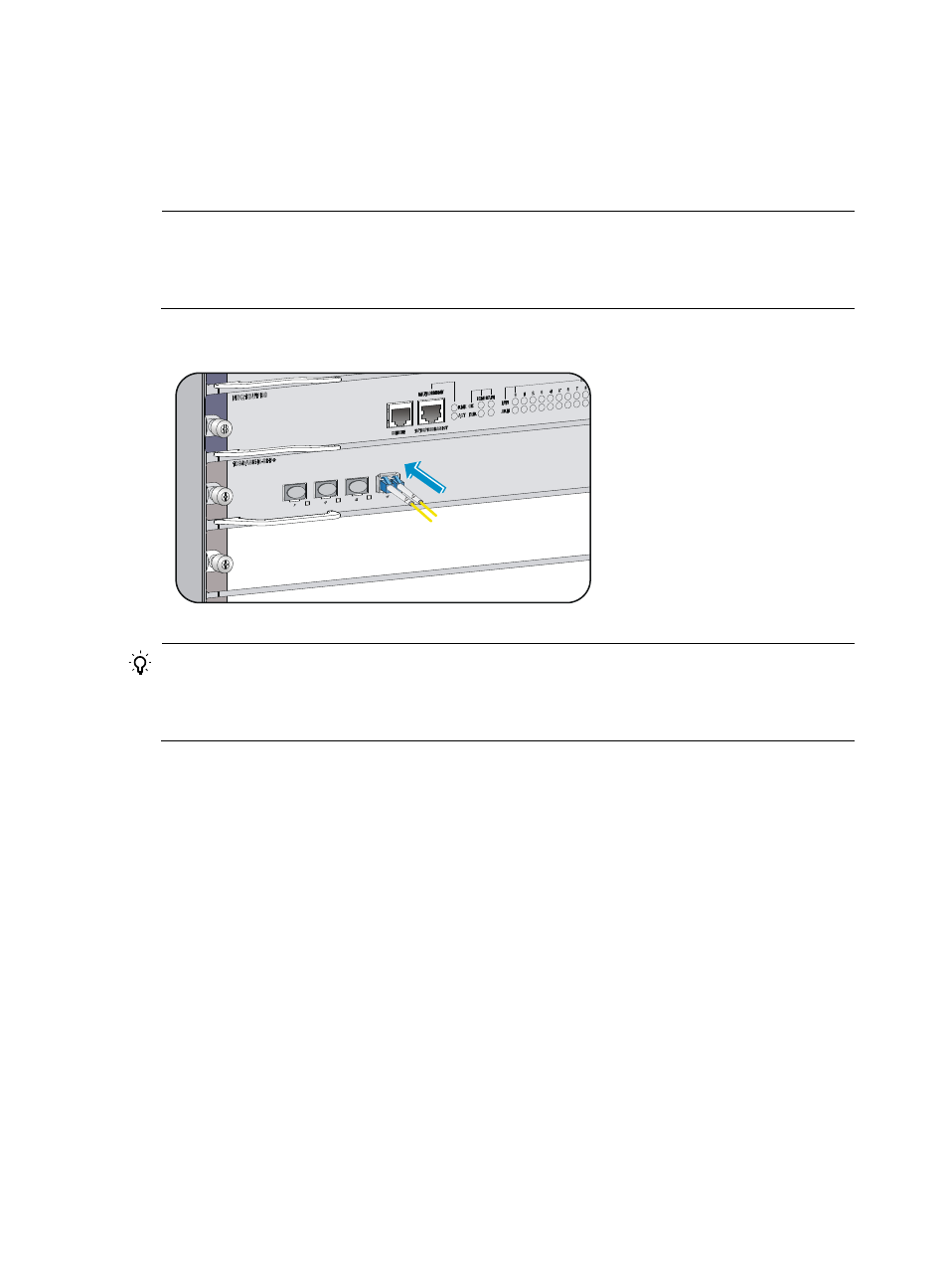
Plug one end of the optical fiber into the transceiver module on the gateway, and plug the other
end into the transceiver module in the peer device.
3.
Examine the port LEDs to verify the connection after the gateway is powered on.
For more information about the LED status, see "Appendix C LEDs."
NOTE:
For the QSFP+ module, you do not need to differentiate between the transmitter (TX) and receiver (RX)
ports. For other types of transceiver modules, the Tx port on one end must connect to the RX port on the
other end.
Figure 22 Connecting a fiber connector to the transceiver module (LC connector)
TIP:
After you connect the gateway into the network, use the ping or tracert command to test the network
connectivity. For more information about these commands, see the configuration guides that come with
your gateway.
Connecting SFP+/QSFP+/QSFP+ to SFP+ cables
For short distance connection, you can:
•
Use SFP+ cables to connect SFP+ ports
•
Use QSFP+ cables to connect QSFP+ ports
•
Use QSFP+ to SFP+ cables to connect QSFP+ and SFP+ ports.
All these cables are hot swappable.
To connect an SFP+, QSFP+, or QSFP+ to SFP+ cable:
1.
Unpack the cable.
2.
Plug the cable connector into the port. Make sure the cable connector is the right side up.
The bend radius of the cable must be at least eight times the cable diameter.