H3C Technologies H3C SecPath M9000 Series User Manual
Page 87
79
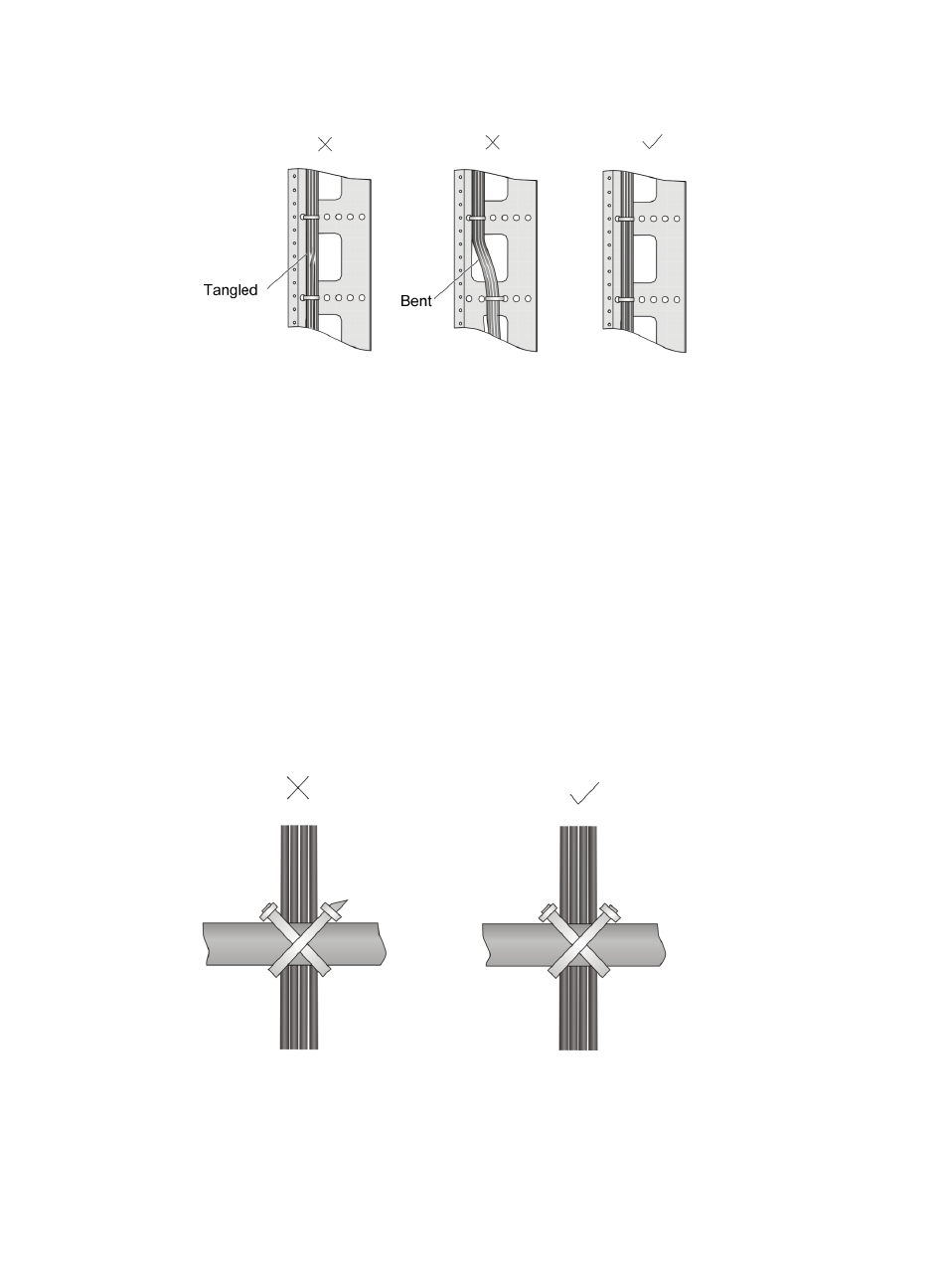
Figure 49 Correct and incorrect cable binding
•
The cable bend radius at connectors must be at least 5 times the cable diameter, and must be at
least twice the cable diameter away from the connectors.
•
Route different types of cables (for example, power cables and signal cables) separately. If they are
close to one another, cross them over one another. If you route them in parallel, make sure the space
between a power cable bundle and a signal cable bundle is at least 30 mm (1.18 in).
•
The cable management brackets and cable routing slots, inside or outside the rack, are smooth and
have no sharp edges or tips.
•
When you route cables through sharp sheet metal penetration points or along sharp edges of
mechanical parts, use bushings or take any other action to protect the cables from being cut or
abraded. The sheet metal penetration points must be smooth and fully rounded.
•
Use the correct type of ties to bind the cables. Do not bind cables with joined ties. The following
types of ties are available: 100 × 2.5 mm (3.94 × 0.10 in), 150 × 3.6 mm (5.91 × 0.14 in), 300 ×
3.6 mm (11.81 × 0.14 in), 530 × 9 mm (20.87 × 0.35 in), and 580 × 13 mm (22.83 × 0.51 in).
•
After binding the cables, cut the excess from the ties, leaving no sharp or angular tips. See
.
Figure 50 Cutting cable ties
•
When you bend cables, bind them as shown in
. To avoid excessive stress causing cable
core break, do not tie up the cables in the bending area.