2 mounting and positioning, 3 interface setup, Changing the interface line setting – iSys V12 Thermal Printer User Manual
Page 13
13
3.2 MOUNTING AND POSITIONING
Keep the V12 plotter away from direct heat sources, including sunlight. Do not block the vents
on the bottom or at the back of the plotter.
The V12 is equipped with rubber feet for absorbing shock in typical situations. Optional
vibration-absorbing mounts are available for rugged environments or mobile situations.
3.3 INTERFACE SETUP
Plug the power cord into a grounded AC outlet only. Avoid sharing an outlet that is also
powering other noise generating equipment.
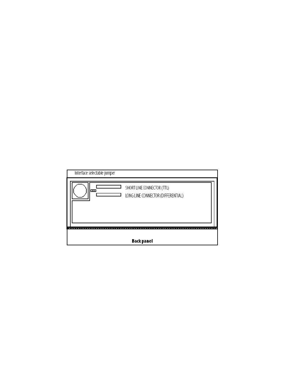
The V12 can be set as either short line (TTL; transistor to transistor logic) or long line
(differential logic) interface. The plotter is shipped with the Versatec interface set for long line
unless otherwise specified. The short line interface can be used for data cable lengths up to 50
feet. The long line interface can be used for data cable lengths up to 700 feet.
For Centronics interface installation, see Appendix A. A SCSI (small computer system
interface) is also available. Please contact your Imaging Systems Group customer service
representative for further information.
Changing the interface line setting
Figure 3-2. Main board interface connections
1. Open the back panel as described in “Procedures” in Chapter 6, Maintenance and Repair.
2. Locate the ribbon cable on the upper left of the board, as viewed from the front of the plotter.
3. Unplug the cable from its port and plug it into the desired line port as shown in Figure 3-
4. Locate the jumper to the left of the ports. Move the jumper to the desired position as shown in
Figure 3-2, matching it to the cable position selection- S or L (Shortline or Longline).
5. Close the back panel and replace the screws.
CAUTION: Do not attempt to plot or form feed without the print medium installed. This may
damage the print head and will void the warranty.