Pilz PSSu E S INC 24V se User Manual
Page 14
Function description
Operating Manual PSSu E S INC 24V se(T)
1001380EN03
14
}
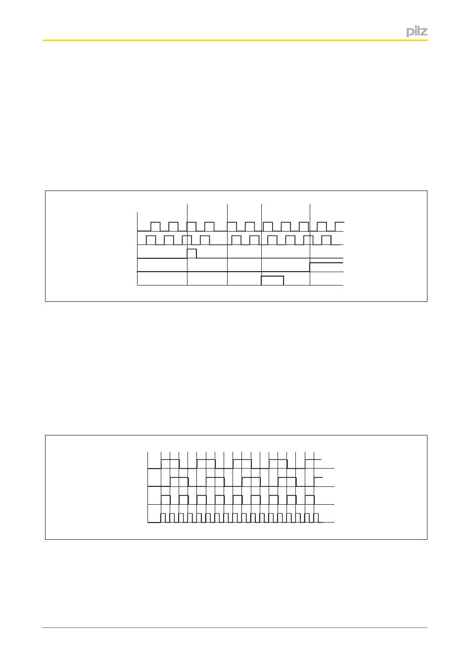
Inputs A, B
The first channel of the encoder is connected to input A, the second to input B. The
second channel is 90° out of phase. If channel A is leading, the module counts for
wards. If channel A is lagging, the module counts backwards (see timing diagram).
}
Input C
The output for the incremental encoder's zero pulse is connected to input C. An incre
mental encoder typically supplies one zero pulse per rotation. If the zero pulse function
is activated, the module copies the last value prior to the zero pulse into the latch
memory and passes it to the process image of inputs (see chapter entitled "Transfer
counter status via latch pulse").
G
L
a
b
c
d
e
C
A
B
Legend:
}
a: The counter counts backwards because the signal at channel A is lagging.
}
b: The module has received a zero pulse. Provided the function is activated, the
counter value is copied into the latch memory with a rising edge at input C.
}
c: The counter counts forwards because the signal at channel A is leading.
}
d: The module has received a latch pulse. Provided the function is activated, the
counter value is copied into the latch memory with a rising edge at input L.
}
e: The counter is disabled because there is a 1 signal at input G.
The module can evaluate the counter pulses once, twice or four times (configuration in the
PSSu Configurator or PAS4000).
B
A
2x
4x
}
Single evaluation:
Each rising edge at channel A increases the counter status.
}
Double evaluation:
Each rising and each falling edge at channel A increases the counter status.