2 transfer counter status via latch pulse, Transfer counter status via latch pulse – Pilz PSSu E S INC 24V se User Manual
Page 16
Function description
Operating Manual PSSu E S INC 24V se(T)
1001380EN03
16
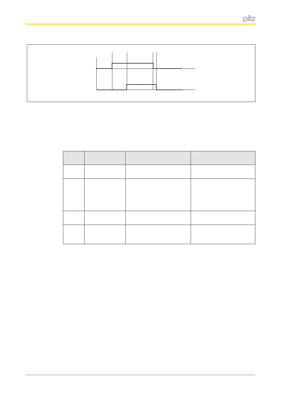
a
PIO
PII
b
c d
Legend:
}
PIO: Bit 1 of the function call in the process image of outputs or I/O data Out
putData.LatchOrMeasure
}
PII: Bit 1 of the status byte in the process image of inputs or I/O data In
putData.LatchOrMeasureDone
Key to timing diagram:
Section Function
Procedure for PSSu in sys
tem environment A
Procedure for PSSu in sys
tem environment B
a
Start measure
ment
In the user program, set Bit 1
of the function call
In the user program, set Out
putData.LatchOrMeasure
b
Output measured
value
Set status bit
Measured value is trans
ferred into the process image
of inputs
The module sets Bit 1 of the
status byte
Measured value is written in
InputData.LatchOrPeriod
The module sets In
putData.LatchOrMeas
ureDone
c
Finish measure
ment
In the user program, reset Bit
1 of the function call
In the user program, reset
OutputData.LatchOrMeasure
d
Ready for new
measurement
The module resets Bit 1 of
the status byte
The module resets In
putData.LatchOrMeas
ureDone
The result of the last period length measurement remains in the process image of inputs
until the module signals a new measurement result by setting the status information. Before
the initial measurement the process image of inputs contains 0000 0000
H
or FFFF FFFF
H
The module issues the result of period length measurement in multiples of 200 ns.
Example:
}
The process image of inputs contains 32
H
/50
D
}
The period length is 200 ns x 50 = 10 μs
4.1.5.2
Transfer counter status via latch pulse
A signal output can be connected to input L on the module for a latch pulse. The latch pulse
may come from a PLC or position switch, for example. Using the latch function it is possible
to record and transmit the counter status at the time of this latch pulse.
Prerequisite: This function is configured in the PSSu Configurator / PAS4000.