2 terminal configuration, Terminal configuration – Pilz PSSu E S INC 24V se User Manual
Page 32
Wiring
Operating Manual PSSu E S INC 24V se(T)
1001380EN03
32
–
Functional earth: 2.5 mm
2
(AWG12)
}
On base modules with screw terminals:
–
If you use a multistrand cable to connect the I/Os, it is recommended that you use
ferrules conforming to Parts 1 and 2 of DIN 46228, 0.14 ... 1.5 mm
2
, Form A or C,
although this is not essential. To crimp the ferrules you can use crimp pliers (crimp
form A or C) conforming to EN 609471, such as the PZ 1.5 or PZ 6.5 from
Weidmüller, for example.
–
Maximum torque setting: 0.8 Nm
}
Use copper wiring.
6.2
Terminal configuration
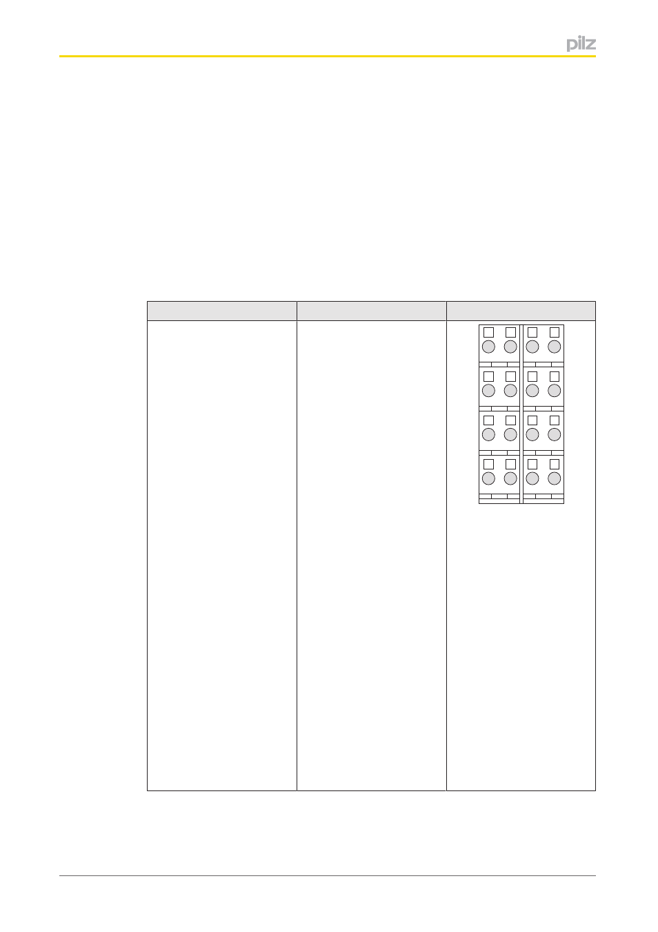
Base module
Terminal configuration
Screw terminals:
PSSu BP 2/16S
PSSu BP 2/16ST
Cage clamp terminals:
PSSu BP 2/16C
PSSu BP 2/16CT
Without Crail:
11: Input A
21: Input B
31: Input C
41: Input G (Gate)
1222: 0 V encoder
(1222 linked within the base
module)
3242: Input S (Status)
(3242 linked within the base
module)
13233343: Cable shield
(13233343 linked within
the base module)
1424: Supply voltage output
for encoder
34: Output for limit value
monitoring
44: Input L (Latch)
21
11
22
12
23
13
24
14
41
31
42
32
43
33
44
34