7 operation, 1 messages, 2 display elements – Pilz PSSu E S INC 24V se User Manual
Page 36: 1 display elements for module diagnostics, Section 7, Operation, Messages, Display elements, Display elements for module diagnostics, 7operation
Operation
Operating Manual PSSu E S INC 24V se(T)
1001380EN03
36
7
Operation
7.1
Messages
A module error is displayed via the "Err" LED (see section entitled "Display elements"), sig
nalled to the head module and then entered in the head module's
}
Error stack, with PSSu in system environment A
}
Diagnostic log, with PSSu in system environment B.
The module can detect the following errors:
Module error
Statement
Remedy
Startup error
Error as the PSSu system starts
up
Change faulty module.
Configuration error
Incorrect module type configured.
The configured hardware registry
does not match the actual hard
ware registry.
ST communication error
Error during ST communication
Change faulty module.
Bus termination error
There is no terminating plate or
there is a bad contact with the
module bus.
Install a terminating plate with in
tegrated end bracket or insert the
base modules together correctly.
Supply voltage overload for en
coder
Supply voltage for encoder over
loaded or shortcircuited
Rectify overload or short circuit
7.2
Display elements
Legend:
LED on
LED off
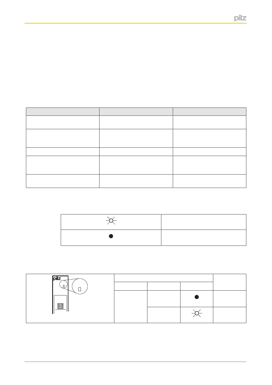
7.2.1
Display elements for module diagnostics
The module has an LED for displaying module errors ("Err" LED).
Err
11
I0
21
I1
Err
LED
Meaning
Name
Colour
Status
Err
No error
Red
Module error