Pilz PSSu E S INC 24V se User Manual
Page 20
Function description
Operating Manual PSSu E S INC 24V se(T)
1001380EN03
20
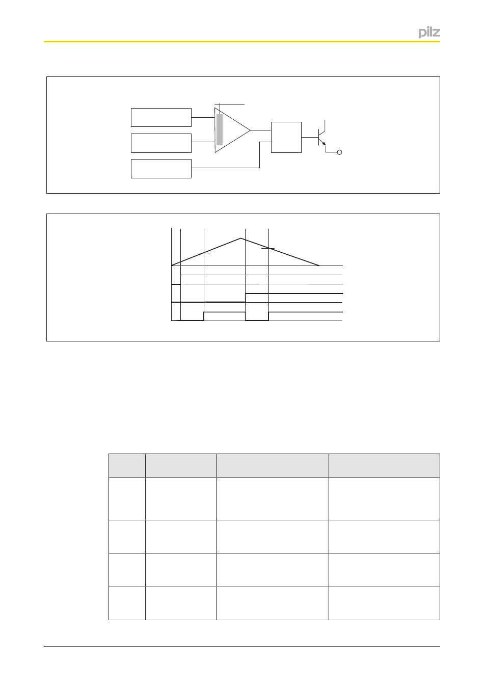
Limit value
Counter status
&
24 V
PIO Bit 3: Enable
+
-
O0
PIO Bit 4:
Polarity
Timing diagram
a
b
PIO (3)
PIO (4)
O0
c
Counter
d
Legend:
}
Counter: Count
}
PIO (3): Bit 3 of the function call in the process image of outputs or I/O datum Out
putData.LimitValueActive
}
PIO (4): Bit 4 of the function call in the process image of outputs or I/O datum Out
putData.InvertOutput
}
O0: Output O0
Key to timing diagram:
Section Function
Procedure for PSSu in sys
tem environment A
Procedure for PSSu in sys
tem environment B
a
Activate monitor
ing function
In the user program, set Bit 3
of the function call. Output
O0 ("0" or "1") is set based
on Bit 4 of the function call
In the user program, set Out
putData.LimitValueActive
b
Limit value
reached
Output O0 ("0" or "1") is set
based on Bit 4 of the function
call
Output O0 ("0" or "1") is set
based on OutputData.Inver
tOutput
c
Output polarity
changed
In the user program, set Bit 4
of the function call. Output
O0 switches polarity
In the user program, set Out
putData.InvertOutput. Output
O0 switches polarity
d
Limit value
reached
Output O0 ("0" or "1") is set
based on Bit 4 of the function
call
Output O0 ("0" or "1") is set
based on OutputData.Inver
tOutput