CIRCUTOR CDP-0 User Manual
Page 12
CDP
12
Instruction Manual
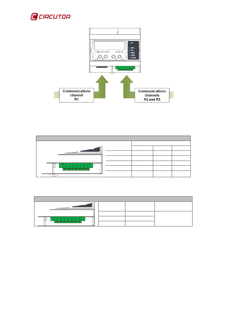
Figure 4:
Communications channels.
The removable connector terminals are described as follows:
Table 5: Description of the R2 channel terminals.
Description of the R2 communications channel connector
Terminals
Description of terminal
RS-422
RS-485 RS-232
1
TxD +
A+
CTS
2
RxD –
NC
(1)
RTS
3
TxD -
B-
RX
4
RxD +
NC
(1)
TX
5
GND
GND
GND
(1)
NC: Not connected.
Table 6: Description of the R3 channel terminals.
Description of the R3 communications channel connector
Terminals
Description
of terminal
Communication
s channel
5
GND
RS-485
6
B-
7
A+
The R2 channel is used for communications with the inverter and the R3 to
create a network with the auxiliary units that help measure the power in three-
phase installations.
Note: For the proper working of RS-485 communications, always connect the
GND terminal.