CIRCUTOR CDP-0 User Manual
Page 13
Advertising
CDP
Instruction Manual
13
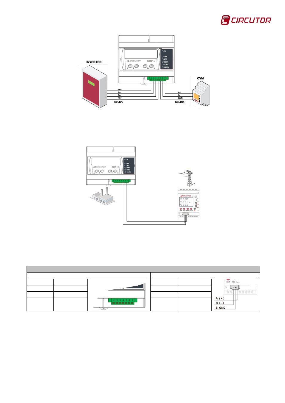
Figure 5: Communications with the inverter and the CVM Mini.
Connection diagram for CDP communications with the external CVM Mini:
Figure 6: CDP connection with the external CVM Mini.
Table 7: Connection of communications between the CDP and the CVM Mini.
Correspondence between the CDP and CVM Mini connection
CDP
CVM MINI
Terminal Description
Terminal Description
5
GND
2
GND
6
B-
1
B-
7
A+
3
A+
To ensure that the CDP can communicate with the external CVM Mini, this must
be configured as per
Advertising
This manual is related to the following products: