Display – CIRCUTOR CDP-0 User Manual
Page 36
CDP
36
Instruction Manual
4.6.- DISPLAY
The CDP includes a 20-character, two-line display which is used as a user
interface.
If the unit is configured to work in single-phase mode, the default screen is
shown in
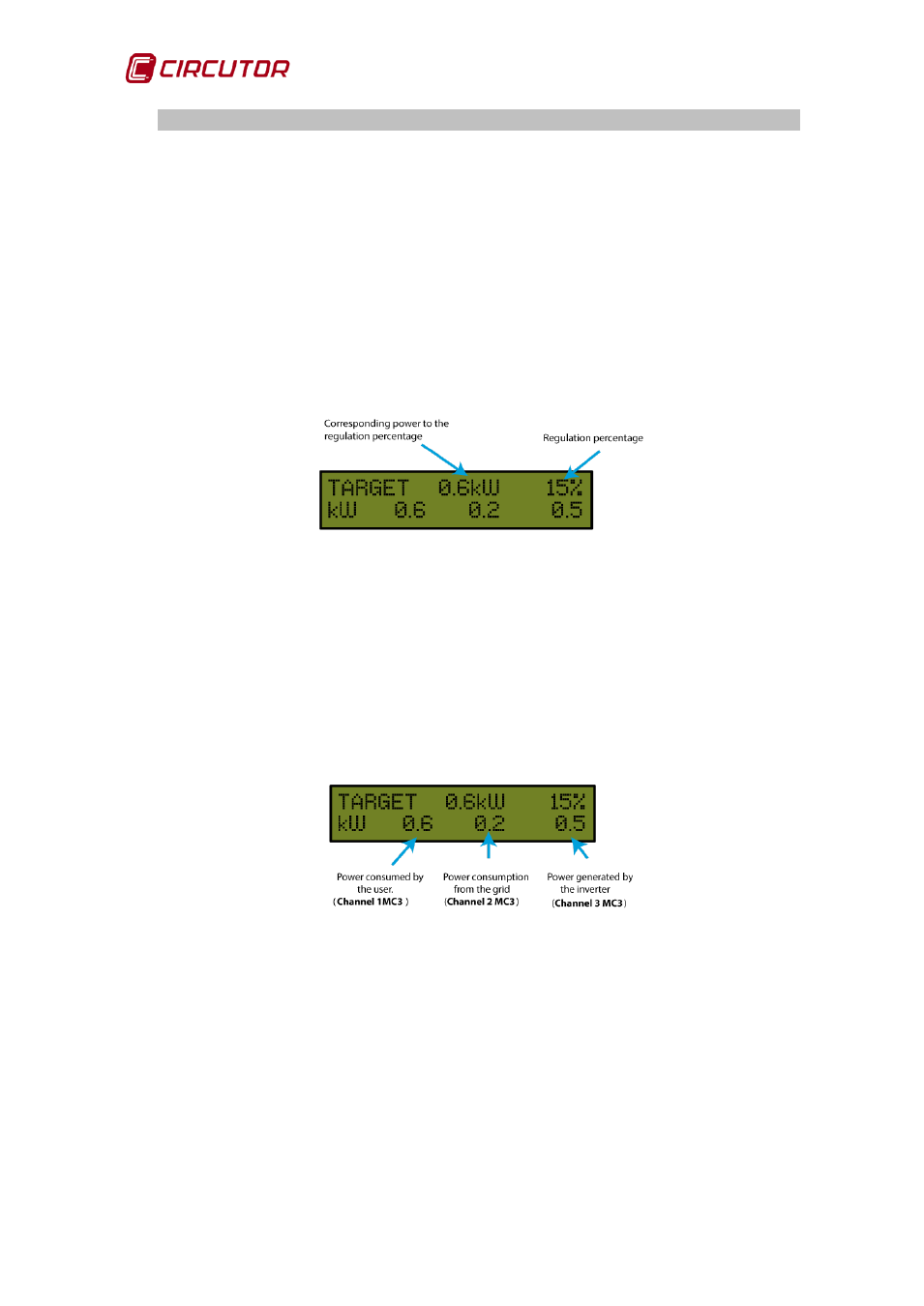
The regulation percentage and corresponding power are indicated on the line
above; in the example shown in the figure below, the nominal power of the
inverter is 4.0 kW and the CDP is sending an order to inject 15%, corresponding
to 0.6 kW.
Figure 32: Description of the first line of the standby screen.
If the connection has been performed correctly, the three power values should
appear with a positive sign. If any of the values appear with a negative sign, this
means that the cable of the phase in question has been connected the other way
round and should therefore be turned.
The power consumption for each of the three measuring channels is indicated
on the line below.
Figure 33: Description of the second line of the standby screen.
If the unit is configured to work in three-phase mode, the default screen is
shown in
The same information as the single-phase configuration is shown on the first
line.
The total three-phase power is shown on the second line.