Indicators – CIRCUTOR CDP-0 User Manual
Page 35
CDP
Instruction Manual
35
4.5.- LED INDICATORS
The CDP has six LEDs so that it is easy for the user to identify the operating
status of the unit.
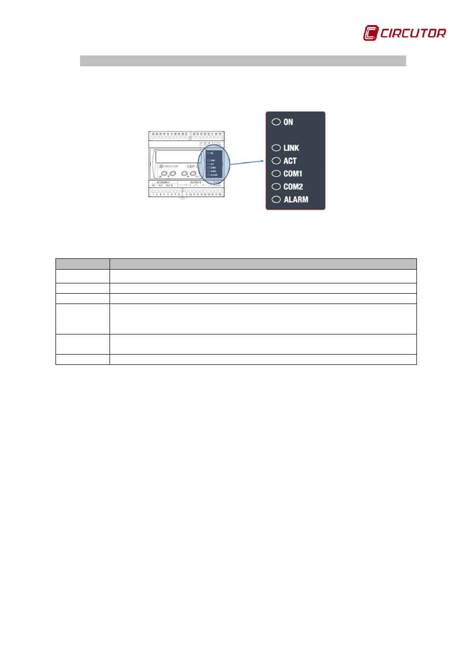
Figure 31: CDP LED indicators.
Table 14: Description of the LED operation.
Function
Description
ON
Flashing mode indicates that the unit is ON (flashes at a rate of 1 second).
LINK
Connection to the active Ethernet network (fixed value).
ACT
Communication frames are being sent (flashing)
COM1
Indicates the communications status of the R2 channel to which the inverters
are connected. In 1 second, the unit flashes as many times as the number of
inverters it has connected and responding.
COM2
Indicates the communications status of the R3 channel through which the
CDP communicates with the auxiliary CVM Mini units (flashing).
ALARM
Indicates the grid injection alarm status. (fixed value)