6 on-chip peripheral bus (opb) configuration, Figure 23: register pdi, Opb interface configuration – BECKHOFF EtherCAT IP Core for Xilinx FPGAs v2.04e User Manual
Page 56
IP Core Configuration
III-44
Slave Controller
– IP Core for Xilinx FPGAs
5.1.5.6
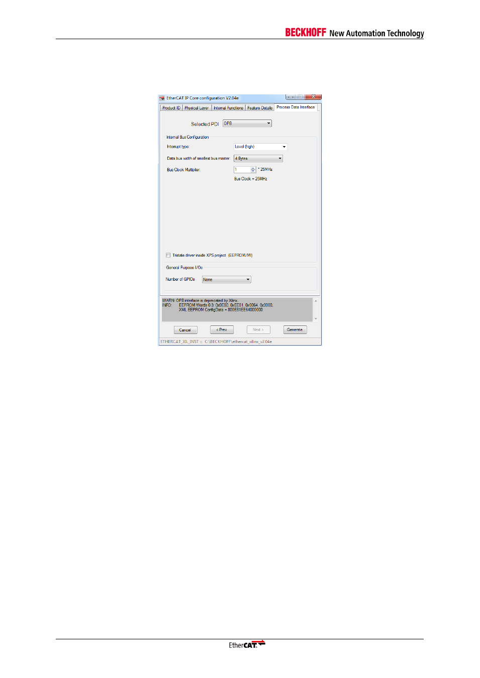
On-Chip Peripheral Bus (OPB) Configuration
The OPB PDI connects the IP Core with an OPB Master (e.g. Xilinx MicroBlaze). The data bus with is
32 bit, and the address bus is also 32 bit wide.
Figure 23: Register PDI
– OPB Interface Configuration
Interrupt type
Select the usage type of the interrupt signal (level or edge). Since the main interrupt can have different
sources, a level based interrupt is typically required.
Data Bus Width of smallest Bus Master
Data bus width of the OPB, counted in bytes (1, 2, or 4 Bytes).
Bus Clock Multiplier
Bus Clock Multiplier (n*25MHz) gives the frequency of the OPB bus clock for communication between
ESC and the OPB master.
Tristate driver inside XPS project (EEPROM/MII)
This option is available if the Tristate drivers are not integrated in the core (Physical Layer tab). It
allows to export the IN/OUT/ENA tristate signals to higher levels above the XPS, or implement the
tristate driver in the XPS.
This additional option is offered in the “Configure IP” dialog of the EtherCAT IP Core instance inside
EDK.