9 ethernet interface, 1 phy management interface, 1 phy management interface signals – BECKHOFF EtherCAT IP Core for Xilinx FPGAs v2.04e User Manual
Page 78: 2 phy address configuration, Ethernet interface, Phy management interface, Phy management interface signals, Phy address configuration, Table 33: phy management interface signals, Figure 26: phy management interface signals
Ethernet Interface
III-66
Slave Controller
– IP Core for Xilinx FPGAs
9
Ethernet Interface
The IP Core is connected with Ethernet PHYs using MII or RMII interfaces. MII is recommended since
the PHY delay (and delay jitter) is smaller in comparison to RMII.
9.1
PHY Management interface
9.1.1
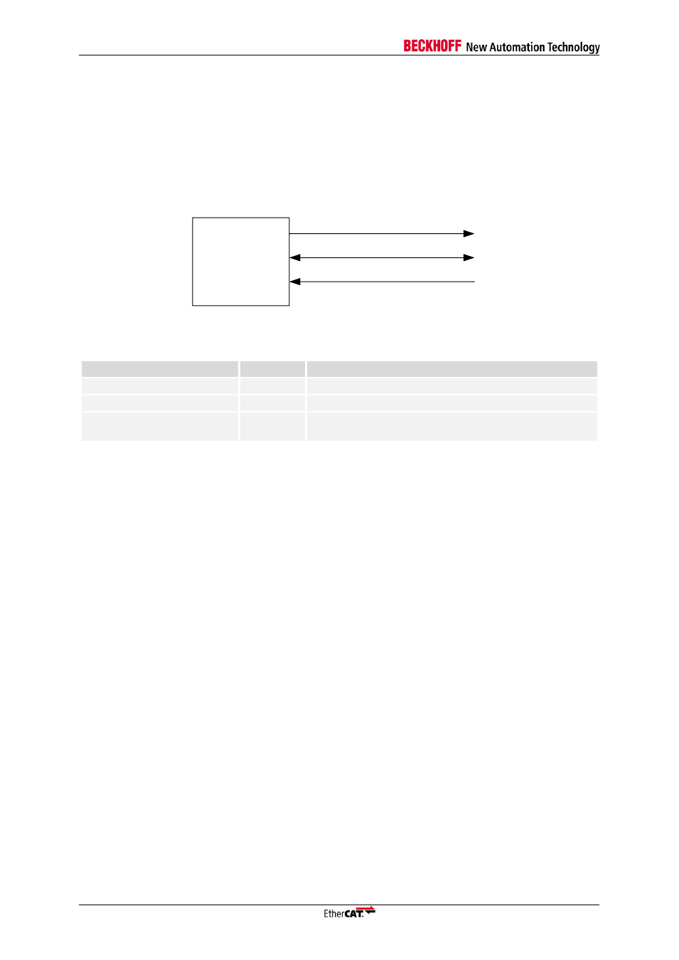
PHY Management Interface Signals
The PHY management interface of the IP Core has the following signals:
EtherCAT
device
MCLK
MDIO
PHY_OFFSET_VEC[4:0]
Figure 26: PHY management Interface signals
Table 33: PHY management Interface signals
Signal
Direction
Description
MCLK
OUT
Management Interface clock (alias MCLK)
MDIO
BIDIR
Management Interface data (alias MDIO)
PHY_OFFSET_VEC[4:0]
INPUT
PHY address offset (consecutive PHY addresses,
address of port 0)
MDIO must have a pull-up resistor (4.7 k
Ω recommended for ESCs), either integrated into the ESC or
externally. MCLK is driven rail-to-rail, idle value is High.
9.1.2
PHY Address Configuration
The EtherCAT IP Core addresses Ethernet PHYs typically using logical port number plus PHY
address offset. Ideally, the Ethernet PHY addresses should correspond with the logical port number,
so PHY addresses 0-2 are used.
A PHY address offset of 0-31 can be applied which moves the PHY addresses to any consecutive
address range. The IP Core expects logical port 0 to have PHY address 0 plus PHY address offset
(and so on).