Maintenance – Beisler 1911-4 User Manual
Page 45
- C 45 -
Short Seam Automat 1911-4 / 1912-4 Working Instructions
Beisler Automated Sewing Equipment
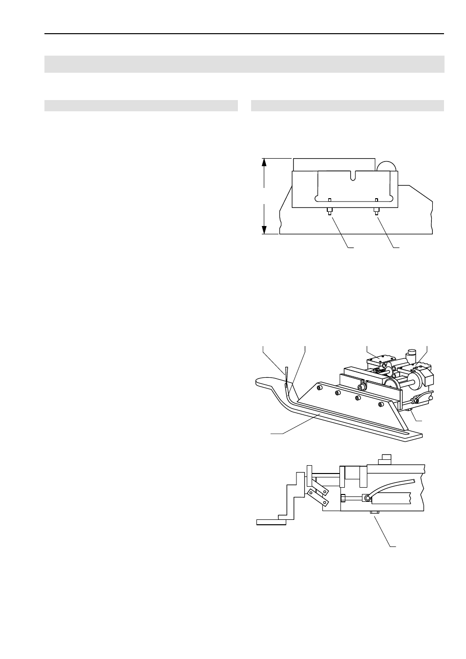
Fig. 12/13
C.5
Maintenance
C.5.5 Machine set-up
After any works to the main clamp, the clamping pressure
and the alignment of the clamp rail to the needle must be
checked.
Clamp rail clamping pressure adjustment:
1. Check to see if the main clamp exerts pressure to the
sewing piece evenly along the entire length of the rail
by lining up a piece of fabric to the insertion position
and lowering the main clamp.
2. Check clamping pressure by trying to pull the sewing
piece out of the clamp at several locations along the
clamp rail.
3. Fig. 12: If clamping pressure is irregular or insufficient,
remove clamp rail and adjust pressure using the two
adjustment screws
1 on the inner side of the clamp
rail.
Tightening the adjustment screws will increase pres-
sure of clamp rail to working plate as the overall height
H of the main clamp increases.
4. Repeat adjustment and recheck with lowered main
clamp until clamping pressure is distributed evenly alo-
ng the entire length of the clamp rail.
Clamp rail position adjustment:
1. Lower main clamp.
2. Depressurize machine by disconnecting the compres-
sed air hose of the machine from the on-site compres-
sed air supply system.
3. Move main clamp manually under sewing head and
use manual drive to lower needle into groove on clamp
rail.
4. Fig. 13: Check to see if needle
1 is centered in groove
2 of clamp rail 4. If not OK, change orientation of
clamp rail to needle.
5. Loosen screw
5 at bottom of main clamp, repositi-
on clamp rail, then tighten screw.
Adjustment of the clamp rail parallel orientation:
1. Check to see if the sewing head needle is positioned
exactly central to the groove along the entire length of
the rail by moving the main clamp under the sewing
head.
2. Fig. 13: If the position is not parallel, loosen eight clamp
bracket retaining screws
3 and move clamp rail to
parallel position.
3. Tighten clamp bracket retaining screws and recheck
parallel orientation of clamp rail.
Fig. 12
Fig. 13
1
1
H
1
2
3
3
4
5
5